News
Industrial PCAP Touch Screen Design Guide: Engineering Reliable Projected Capacitive Touch Displays for Demanding Environments
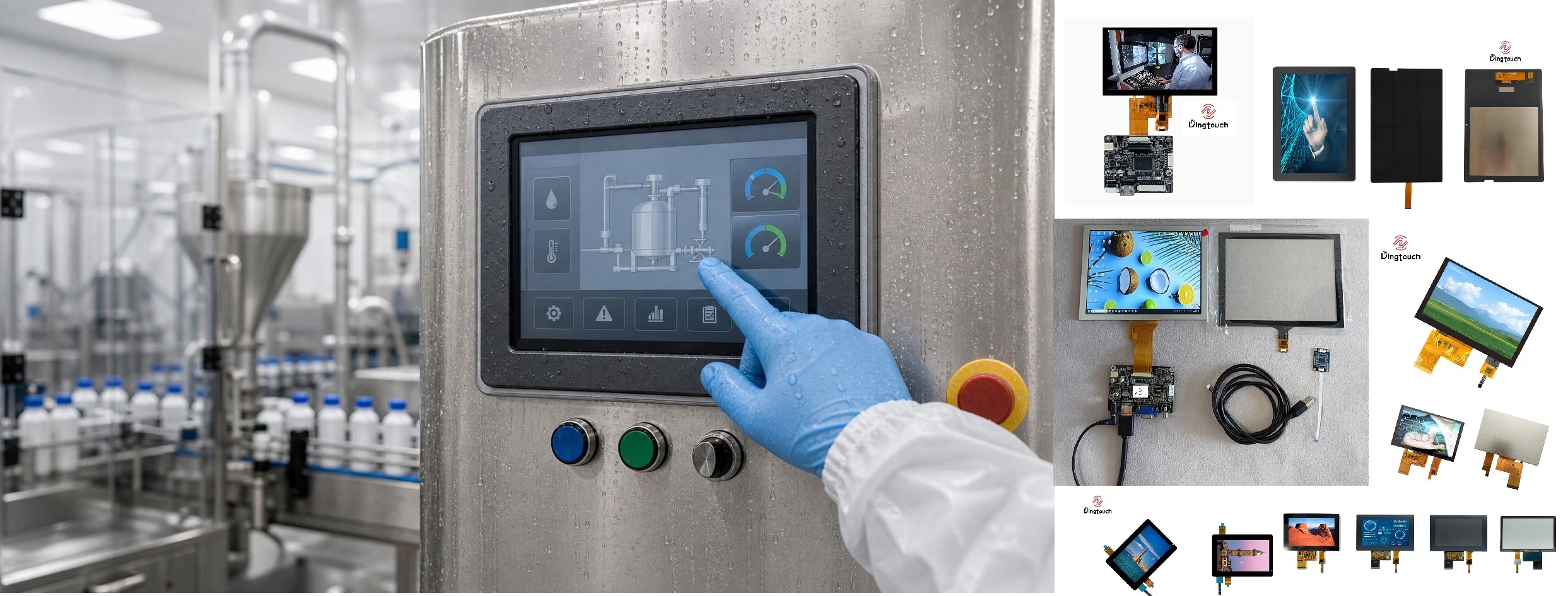
From Cover Glass and Glove Touch to Water Rejection, EMI Protection, and Optical Bonding
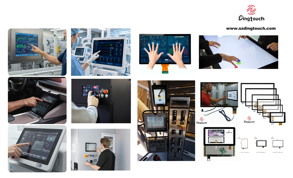
Selecting a reliable display for industrial HMI, medical carts, outdoor kiosks, EV chargers, marine electronics, smart home control panels, and rugged handheld devices is rarely determined by a single specification.
Projected Capacitive Touch (PCAP) technology has become a preferred solution for modern industrial human-machine interfaces because of its responsive operation, multi-touch capability, durable glass surface, and excellent optical performance.
However, industrial applications introduce additional engineering challenges. Thick cover glass, protective gloves, water droplets, metal enclosures, electromagnetic interference, grounding differences, and mechanical tolerances can all affect touch stability.
A common problem in display development is that a PCAP touch panel performs well during open-frame testing but becomes unreliable after installation in the final product enclosure. Typical symptoms include false touches, missed inputs, unstable tracking, and reduced sensitivity when operated with gloves.
This demonstrates why industrial PCAP touch screen should not be treated as standalone touch sensors. They must be designed, tuned, and validated as part of a complete display system.
As a manufacturer specializing in industrial capacitive touch screens and customized touch display modules, DINGTouch has 15 years of experience in industrial touch display customization. Our capabilities cover PCAP touch sensors, TFT LCD modules, custom cover glass, touch display integration, and full optical bonding.
This engineering guide explains the key considerations for designing reliable industrial PCAP touch displays, helping OEM manufacturers, product designers, and engineering teams make informed decisions during product development.
1. What Is an Industrial PCAP Touch Screen and Why Does Engineering Design Matter?
Projected Capacitive Touch (PCAP) is a touch-sensing technology that detects changes in capacitance caused by a finger or another conductive object approaching or contacting the touch surface.
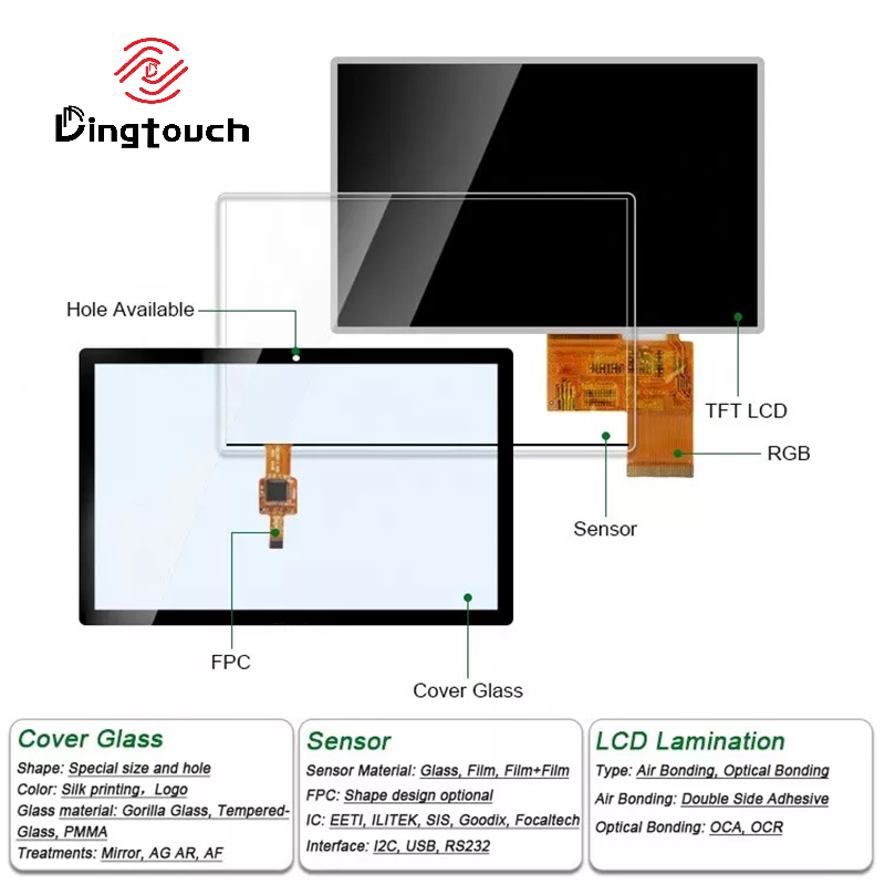
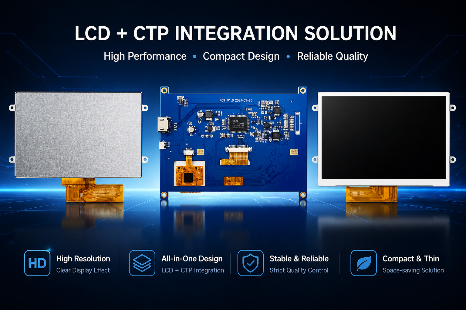
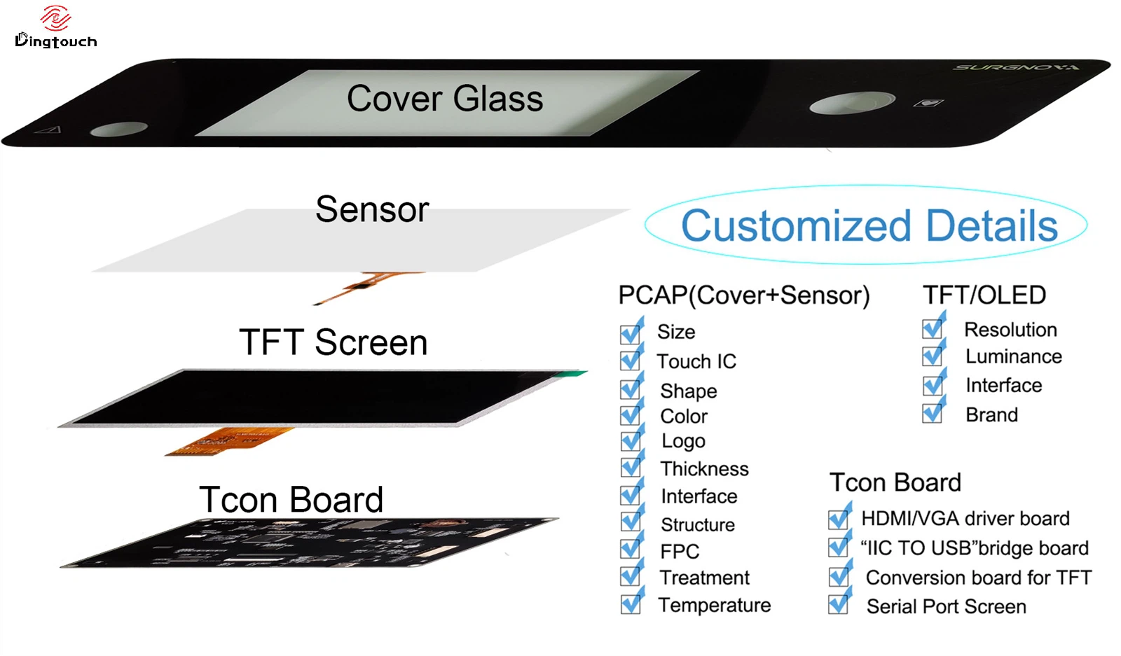
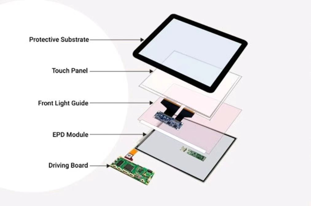
A typical industrial PCAP touch display consists of several integrated components:
-
Cover Glass: Protects the touch sensor and provides a durable user interface.
-
Touch Sensor: Detects changes in the electrical field caused by touch.
-
Touch Controller: Processes touch signals and determines touch coordinates.
-
FPC: Provides electrical connections between the sensor and controller.
-
LCD Module: Displays visual information.
-
Bonding Layer: Connects optical components using an appropriate bonding material.
In a typical industrial touch display module, the PCAP sensor connects to the touch controller through an FPC cable. The controller then communicates with the host system through interfaces such as I2C or USB.
Depending on the mechanical design and application requirements, different sensor structures can be evaluated, including G+G (Glass + Glass), G+F (Glass + Film), and other customized configurations.
1.1 How Is Industrial PCAP Different from Consumer Touch Screens?
Industrial PCAP touch screen must satisfy more than basic touch sensitivity requirements.
| Engineering Area | Industrial Design Considerations |
|---|---|
| Cover Glass | Thickness, mechanical strength, surface treatment, and protection |
| Touch Performance | Multi-touch, glove operation, and wet-finger recognition |
| Electrical Performance | EMI immunity, ESD protection, and grounding stability |
| Environmental Resistance | High and low temperatures, humidity, and condensation |
| Optical Performance | Transmittance, reflection, glare, and readability |
| Mechanical Integration | Enclosure design, sealing, tolerances, and vibration |
| Product Lifecycle | Supply stability, batch consistency, and maintainability |
For industrial equipment manufacturers, a reliable PCAP solution must maintain stable performance inside the final product, not just under controlled laboratory conditions.
2. Cover Glass Design: Thickness, Sensor Geometry, and Touch Sensitivity
Cover glass is one of the most important mechanical and optical components in an industrial PCAP touch display.
It protects the internal touch sensor while directly influencing touch signal strength, operating experience, display clarity, and product durability.
2.1 How Does Cover Glass Thickness Affect Touch Performance?
When a finger approaches the glass surface, the touch controller detects a small change in capacitance through the sensor electrodes.
Generally, increasing cover glass thickness increases the distance between the finger and the touch sensor, which can reduce the available touch signal.
Therefore, a standard PCAP sensor designed for 0.7 mm cover glass may not perform reliably with 3 mm, 6 mm, or even thicker industrial protective glass without further evaluation and tuning.
Important design factors include:
-
Cover glass thickness
-
Glass dielectric properties
-
Sensor electrode size and layout
-
Distance between the sensor and cover glass
-
Printed ink borders and active touch area
-
Touch controller sensitivity and signal processing capability
-
Enclosure and grounding configuration
For applications requiring vandal resistance, impact protection, or medical-grade cleaning compatibility, the cover glass specification should be confirmed early in the project.
Touch performance should then be evaluated using the actual glass configuration.
2.2 How to Select Industrial PCAP Cover Glass
DINGTouch can evaluate different cover glass structures and surface treatments according to application requirements.
Common options include:
-
Chemically Strengthened Glass: Improves mechanical strength and resistance to surface damage.
-
AG (Anti-Glare): Reduces surface glare and improves visibility under ambient lighting.
-
AR (Anti-Reflection): Reduces reflections and improves display readability.
-
AF (Anti-Fingerprint): Helps reduce fingerprint residue and simplifies cleaning.
-
Custom Silk-Screen Printing: Supports product appearance and mechanical design requirements.
-
Custom-Shaped Glass: Accommodates special enclosure dimensions and installation structures.
AG, AR, and AF are different surface treatment technologies. Their performance and suitability should be evaluated according to the actual operating environment.
3. Glove Touch: How to Enable Reliable Industrial touchscreen Operation with Gloves
Glove operation is an important requirement for many industrial PCAP applications.
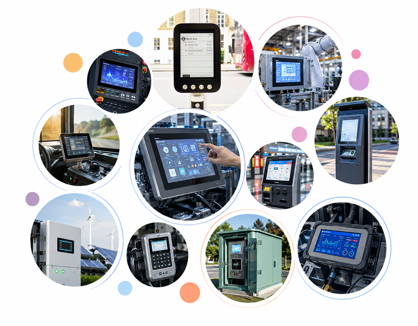
Operators in industrial automation, medical equipment, logistics terminals, outdoor control systems, and agricultural machinery may need to interact with touch displays while wearing different types of gloves.
Common examples include:
-
Nitrile Gloves
-
Latex Gloves
-
Leather Work Gloves
-
Winter Gloves
-
Coated Industrial Gloves
-
Multi-Layer Protective Gloves
Different glove materials, thicknesses, and moisture levels affect capacitive coupling between the user's finger and the touch sensor.
3.1 Why Do Some PCAP Touch Screens Fail to Recognize Gloved Fingers?
Several factors can reduce glove touch performance:
-
Gloves reduce capacitive coupling between the finger and touch surface.
-
Thick cover glass further reduces the available touch signal.
-
The sensor electrode geometry may not be optimized for low-signal input.
-
Controller sensitivity and filtering parameters may be incorrectly configured.
-
Metal enclosures or grounding structures may interfere with touch signal detection.
3.2 How to Improve Glove Touch Performance
Several engineering approaches can help improve glove operation:
-
Select a PCAP controller suitable for glove-touch applications.
-
Optimize sensor electrode geometry and sensing area.
-
Adjust touch sensitivity according to cover glass thickness.
-
Optimize noise filtering and touch thresholds in the controller firmware.
-
Validate performance using the actual gloves specified by the customer.
It is important to understand that glove-touch support does not mean compatibility with every type of glove.
DINGTouch recommends that customers provide representative glove samples during project development. This allows the touch solution to be evaluated according to glove material, thickness, and actual operating conditions.
4. Water Rejection: How to Solve Water-Related Problems in Industrial PCAP Touch Screen
Water is one of the important factors affecting PCAP touch performance.
When water droplets, continuous water films, or wet fingers contact the glass surface, they can change the electrical field around the touch sensor. This may cause false touches, unstable tracking, or missed inputs.
Water-related performance is especially important for outdoor kiosks, medical equipment, food-processing machinery, marine control panels, and EV charging stations.
4.1 Why Can Water Cause False Touches?
PCAP technology relies on detecting changes in capacitance.
Water droplets may create localized conductive areas or electrical coupling between sensor electrodes. The controller may interpret these changes as human touch events.
Typical problems include:
-
Random touches when nobody is operating the display.
-
Inaccurate positioning when using wet fingers.
-
Difficulty distinguishing multiple touch points.
-
Touch failures in areas covered by water droplets.
-
False inputs during cleaning or wiping.
4.2 How to Improve Water Rejection in Industrial PCAP Designs
DINGTouch recommends evaluating three main areas.
1. Sensor and Controller Design
Select a touch controller with appropriate water-rejection algorithms or wet-operation capabilities. Controller parameters should be tuned according to the actual sensor and cover glass configuration.
2. Cover Glass Surface Treatment
AF coatings and other suitable surface treatments can improve cleaning performance and influence how water interacts with the glass surface. However, surface coatings cannot replace proper touch-controller water-rejection tuning.
3. Complete Enclosure Sealing
Design appropriate gaskets, enclosure structures, and connector protection to prevent water from entering the display module.
An important distinction must be made: PCAP water-rejection capability and enclosure IP65/IP67 protection are two different requirements.
Water rejection concerns touch behavior under wet conditions, while IP ratings describe the enclosure's tested resistance to dust and water ingress. Both must be evaluated independently.
5. EMI Immunity: Electromagnetic Interference and Grounding Design for Industrial touch screens
Industrial equipment often contains motors, variable-frequency drives, switching power supplies, wireless communication modules, and other electronic components.
These devices may generate electromagnetic noise that interferes with the touch controller's ability to detect small capacitance changes.
Therefore, EMI (Electromagnetic Interference) is an important consideration in industrial touch display design.
5.1 What Can Cause PCAP Touch Instability?
Common sources of interference include:
-
Conducted noise from switching power supplies.
-
Electromagnetic noise generated by LCD backlight driver circuits.
-
Excessively long or poorly routed FPC cables.
-
Improper grounding of metal enclosures.
-
High-frequency signals near the touch controller.
-
Wireless communication modules located too close to the touch sensor.
-
Electrical noise and ground potential differences in the system.
5.2 How to Improve EMI Performance
Several areas should be reviewed during engineering development.
PCB Layout
Keep the touch controller away from high-noise circuits and establish appropriate power and ground routing.
FPC Design
Optimize FPC length, routing, and shielding according to the electrical interface and mechanical requirements.
Grounding Strategy
Define the grounding relationship between the touch sensor, LCD module, metal enclosure, and host motherboard.
Power Management
Optimize power filtering and backlight driver layout to reduce noise coupling.
Shielding Measures
Depending on test results, consider shielding layers, driven shielding, or ferrite components.
Adding shielding does not automatically solve every EMI problem. Incorrect grounding or shielding can introduce additional parasitic capacitance and unwanted interference paths.
Therefore, EMI and ESD performance should be verified in the final product configuration while monitoring touch functionality.
6. Touch Controller Tuning: Firmware Configuration and Signal Optimization
PCAP touch performance depends not only on the sensor itself but also on the touch controller and its firmware algorithms.
Even when using the same sensor size, changes to the cover glass, FPC, bonding materials, or enclosure may alter the electrical characteristics of the complete touch system.
Controller tuning must therefore match the final product structure.
6.1 Which Parameters Require Special Attention?
Common touch-controller parameters include:
-
Touch Sensitivity
-
Noise Filtering
-
Touch Threshold
-
Water Rejection
-
Glove Mode
-
Baseline Tracking
-
Multi-Touch Recognition
-
Palm Rejection
Parameter names, algorithms, and tuning methods vary between touch controller manufacturers.
6.2 Why Should Firmware and Tuning Versions Be Locked Before Mass Production?
Replacing a touch sensor, changing cover glass thickness, modifying bonding materials, or changing the FPC configuration during production can affect touch performance, even when the external dimensions remain unchanged.
DINGTouch recommends establishing an engineering version-control process that includes:
-
Touch sensor drawing revision.
-
Cover glass specifications and thickness.
-
FPC design revision.
-
Touch controller model and firmware version.
-
Controller tuning files.
-
Approved engineering samples.
-
Mass-production inspection standards.
During project approval, a standard reference sample should be established for comparison with subsequent production batches and quality inspections.
7. Optical Bonding: How Does Full Lamination Affect Industrial PCAP Touch Displays?
In industrial touch display modules, optical bonding improves more than just display appearance. It can also change the electrical environment surrounding the touch sensor.
Common bonding methods include:
-
Air Gap Bonding
-
OCA (Optically Clear Adhesive) Bonding
-
LOCA (Liquid Optically Clear Adhesive) Bonding
7.1 Main Advantages of Optical Bonding
Compared with traditional air-gap structures, optical bonding reduces the number of reflective interfaces between the cover glass and LCD.
Key benefits include:
-
Improved outdoor display readability.
-
Reduced internal reflections and glare.
-
Better visual clarity.
-
Reduced risk of dust and moisture accumulating in internal air gaps.
-
Improved structural integration of the display module.
7.2 Can Optical Bonding Affect Touch Performance?
Yes, it can.
The dielectric properties and thickness of the bonding material, bonding uniformity, and sensor positioning can all influence the electrical characteristics of the complete touch stack.
Therefore, the PCAP sensor, cover glass, bonding layer, and LCD module should be evaluated as one integrated structure.
DINGTouch provides LCD modules, PCAP touch sensors, custom cover glass, and full optical bonding capabilities. We can evaluate integrated touch display solutions according to customer requirements for dimensions, display interfaces, touch functions, and operating environments.
8. Mechanical Integration: Enclosure Design, FPC Routing, and Assembly
In actual OEM projects, mechanical installation can significantly influence touch display performance.
Even if the PCAP sensor and controller meet their individual specifications, an unsuitable mechanical structure may cause touch abnormalities after assembly.
8.1 Key Mechanical Design Considerations
Cover Glass and Enclosure Clearance
Avoid uneven pressure from the enclosure directly onto the cover glass. Maintain appropriate clearance between the glass and mounting frame.
Gasket Design
Gasket compression, material selection, and positioning should be carefully evaluated to avoid changing the electrical environment around the touch sensor.
FPC Bending and Fixing
Avoid excessive FPC bending, stretching, and concentrated mechanical stress. Connectors should have reliable mechanical support.
Metal Enclosure and Grounding
Define the grounding relationship between the metal enclosure and touch system during the early mechanical design stage.
Assembly Repeatability
Ensure consistent glass positioning, sensor alignment, bonding thickness, and connector installation during mass production.
For high-reliability industrial equipment, actual assembly testing should be completed before design freeze rather than relying solely on two-dimensional mechanical drawings.
9. Industrial PCAP Touch Display Validation: How to Verify Long-Term Reliability
PCAP touch display validation should not be limited to testing an exposed module on a laboratory bench.
A meaningful engineering validation sample should closely represent the final production configuration.
9.1 Build a Complete Engineering Validation Sample
The sample should include:
-
Final cover glass.
-
Actual PCAP touch sensor.
-
Confirmed OCA or LOCA bonding structure.
-
LCD display module.
-
Production-length FPC and connectors.
-
Actual backlight driver circuit.
-
Final metal or plastic enclosure.
-
Gaskets and mounting structures.
-
Approved touch controller firmware.
9.2 Recommended Validation Tests
| Test Item | Main Evaluation Focus |
|---|---|
| Touch Accuracy | Touch positioning accuracy |
| Multi-Touch | Multi-point recognition stability |
| Glove Touch | Performance with specified gloves |
| Wet Touch | Wet-finger and water-droplet operation |
| EMI | Touch stability under electromagnetic interference |
| ESD | Functional recovery after electrostatic discharge |
| Temperature | Touch performance at high and low temperatures |
| Humidity | Resistance to high-humidity conditions |
| Vibration | Structural and touch stability after vibration |
| Power Cycling | Performance after repeated power cycles |
| Long-Term Operation | Stability during extended operation |
Specific test levels, temperature ranges, vibration conditions, and ESD requirements should be determined according to the equipment application, target market, and applicable standards.
9.3 Do Not Ignore Real Operating Conditions
For outdoor equipment, validate the display under strong sunlight, rain exposure, and temperature changes.
For medical devices, consider cleaning agents, disinfection procedures, glove operation, and the electromagnetic compatibility requirements of the complete device.
For industrial automation, focus on the effects of motors, variable-frequency drives, power systems, and metal enclosures.
For marine and transportation equipment, consider vibration, humidity, temperature variations, and continuous operation.
The ultimate objective is not simply to make the touch screen work in a laboratory. It is to ensure stable performance in the actual equipment throughout its intended service life.
10. PCAP Touch Screen Selection: Procurement and Supply Chain Management
For OEM and ODM equipment manufacturers, a touch display is more than an electronic component. It is a critical subsystem that influences product reliability and lifecycle management.
During procurement, engineering teams should request more than a quotation.
10.1 Technical Documentation
Recommended documents include:
-
TFT LCD datasheets.
-
PCAP sensor specifications and structural drawings.
-
Touch controller model information.
-
FPC and interface definitions.
-
Display interface and timing specifications.
-
Backlight electrical specifications.
-
Mechanical dimension drawings.
10.2 Quality and Reliability Documentation
Depending on the application, request:
-
Relevant reliability test reports.
-
RoHS and REACH compliance documentation, where applicable.
-
Production inspection specifications.
-
Product revision and change-control records.
-
Packaging and transportation specifications.
10.3 Product Lifecycle Management
Important considerations include:
-
LCD panel availability.
-
Touch controller and critical IC supply stability.
-
Alternative sources for key materials.
-
Product Change Notification (PCN) procedures.
-
Long-term supply planning and alternative solutions.
DINGTouch recommends defining the target order quantity, expected production schedule, service life, and key performance requirements early in the project. This allows the product platform, customization costs, and potential supply risks to be evaluated in advance.
11. Why Choose DINGTouch for Custom Industrial PCAP Touch Display Solutions?
DINGTouch is a manufacturer specializing in the R&D, production, and sales of industrial capacitive touch screens, TFT LCD modules, and integrated touch display solutions.
Beyond standard PCAP touch screen, we provide customized display solutions for different industrial applications.
DINGTouch Manufacturing and Engineering Capabilities
1. PCAP Touch Sensor Customization
Evaluate sensor structures, dimensions, FPC configurations, touch controllers, and touch functions according to project requirements.
2. Custom Cover Glass
Support different thicknesses, dimensions, shapes, and surface treatments, including AG, AR, and AF.
3. TFT LCD Integration
Provide industrial TFT LCD modules in various sizes and resolutions, with project-based evaluation of brightness, interfaces, and operating temperatures.
4. Optical Bonding Manufacturing
Support OCA and LOCA bonding solutions to optimize the optical structure of integrated touch display modules.
5. Industrial Environmental Adaptation
Evaluate glove touch, wet operation, high-brightness outdoor displays, wide-temperature operation, and EMI resistance according to application requirements.
6. OEM/ODM Project Support
Provide one-to-one engineering support throughout project evaluation, mechanical drawing preparation, sample development, and mass-production introduction.
With integrated R&D and manufacturing capabilities, DINGTouch can coordinate the evaluation of LCD, PCAP, cover glass, and optical bonding structures.
This helps customers reduce communication costs between multiple suppliers and improve product development efficiency.
Our objective is not simply to supply a display that powers on. We aim to help customers develop reliable, manufacturable industrial touch display solutions tailored to real operating conditions.
12. Engineering Checklist: Industrial PCAP Touch Screen Design Review
Before approving an industrial PCAP touch display solution, engineering teams should review the following items:
-
Confirm cover glass material, thickness, and surface treatment.
-
Confirm PCAP sensor structure and active touch area.
-
Confirm touch controller and host interface.
-
Define supported glove materials and thicknesses.
-
Validate wet-finger operation, water droplets, and cleaning conditions.
-
Check FPC length, routing, and connector structure.
-
Confirm metal enclosure and system grounding design.
-
Verify optical bonding materials and bonding thickness.
-
Perform EMI and ESD tests in the final enclosure.
-
Validate high/low-temperature and long-term operating performance.
-
Lock firmware, tuning files, and engineering sample revisions.
-
Confirm key material availability and product lifecycle planning.
13. Final Recommendation: Design PCAP as a Complete Industrial Touch Display System
The reliability of an industrial PCAP touch display is not determined by a single touch controller or sensor.
Cover glass, sensor electrodes, controller algorithms, FPC routing, electrical grounding, optical bonding materials, mechanical enclosure design, and real operating conditions all influence final touch performance.
For industrial equipment manufacturers, the most effective approach is to design and validate the touch system as part of the complete product structure from the beginning of development.
DINGTouch combines PCAP touch sensor integration, TFT LCD solutions, custom cover glass, and optical bonding manufacturing to support industrial automation, medical equipment, outdoor terminals, and other demanding applications.
If your project requires thick cover glass, glove operation, wet-touch performance, EMI resistance, or customized touch display dimensions, contact DINGTouch with your application requirements, mechanical drawings, or reference specifications.
Our engineering team can help evaluate a suitable PCAP touch display architecture for your project.
DINGTouch – Industrial Touch Display Solutions Manufacturer
Website: www.szdingtouch.com
Email: sales@szdingtouch.com
Frequently Asked Questions (FAQ)
1. Can industrial PCAP touch screen work with gloves?
Yes. Industrial PCAP touch screen can be designed for glove operation. However, performance depends on glove material, thickness, cover glass, sensor design, controller capability, and firmware tuning. Specific glove samples should be tested during project development.
2. Why does water affect projected capacitive touch screen?
Water changes the electrical characteristics around the touch sensor. Water droplets or continuous water films may cause false touches, unstable tracking, or missed inputs. Water-rejection performance must be evaluated using the final sensor and controller configuration.
3. What is the maximum cover glass thickness for an industrial PCAP touch screen?
There is no universal maximum thickness. Thicker glass generally reduces touch signal strength. The achievable thickness depends on sensor geometry, controller capability, glass properties, bonding structure, and grounding conditions.
4. Does optical bonding improve PCAP touch display performance?
Optical bonding primarily improves optical performance by reducing internal reflections and air gaps. It can also change the electrical characteristics of the complete touch stack, so touch performance should be evaluated after bonding.
5. Can PCAP touch screen work inside metal enclosures?
Yes, but metal enclosures can influence the electric field and grounding characteristics of the touch system. Proper sensor layout, grounding, FPC routing, and controller tuning are important.
6. What is the difference between PCAP water rejection and IP65/IP67 protection?
PCAP water rejection refers to the touch controller's ability to maintain stable touch behavior in wet conditions. IP65 and IP67 refer to the enclosure's tested protection against dust and water ingress. They are different performance requirements and should be validated separately.
7. What information is required for a custom industrial PCAP touch display project?
Useful project information includes display size, resolution, brightness, interface, cover glass dimensions and thickness, touch points, glove requirements, operating temperature, mechanical drawings, and target application.
8. Does DINGTouch provide complete industrial PCAP touch display solutions?
Yes. DINGTouch can provide project-based solutions integrating PCAP touch sensors, TFT LCD modules, custom cover glass, and optical bonding. Specifications are evaluated according to the customer's application and mechanical requirements.
DINGTouch:Committed to continuous innovation and improvement of product quality to meet customers' high requirements and expectations.
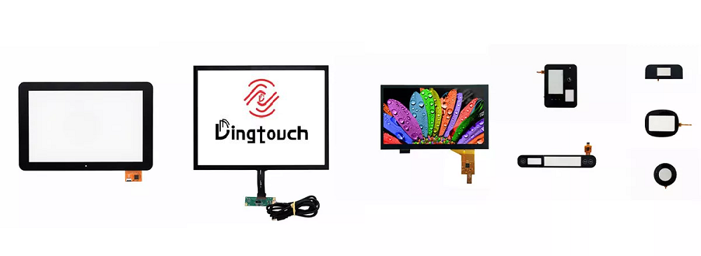
DINGTouch is a manufacturer that provides high quality touch screen panels. Focus on the design, manufacturing and sales of touch screen panels, and are committed to providing customized solutions that satisfy customers.
DINGTouch: In the process of customizing touch screen panels, we focus on close cooperation and communication with customers. Understanding customers' needs and providing customized solutions will meet customers' individual needs. The company's products are favored by customers for their high quality and reliability, and provide them with the best touchscreen panel solutions.
DINGTouch:Committed to continuous innovation and improvement of product quality to meet customers' high requirements and expectations.
DINGTouch is a manufacturer that provides high quality touch screen panels. Focus on the design, manufacturing and sales of touch screen panels, and are committed to providing customized solutions that satisfy customers.
DINGTouch: In the process of customizing touch screen panels, we focus on close cooperation and communication with customers. Understanding customers' needs and providing customized solutions will meet customers' individual needs. The company's products are favored by customers for their high quality and reliability, and provide them with the best touchscreen panel solutions.
At DINGTOUCH, we are the world's leading touchscreen manufacturer, helping businesses around the world take advantage of this exciting technology. For more information, please visit the home page now.

DINGTouch is a company specializing in the R&D and production of touch screen technology, headquartered in Shenzhen, China. As a professional touch screen supplier, DINGTouch is committed to providing high-quality, stable and reliable touch screen products to meet the diverse needs of customers. We continue to carry out technological innovation and product optimization to ensure that its touch screen products have good sensitivity, accuracy and durability.
CATEGORIES
CONTACT US
Contact: Dingtouch
Phone: +8615815536116
Tel: +8615815536116
Email: sales@szdingtouch.com
Add: Building A, Bailu Plaza, No. 48, Gonghe Industrial Road, Gongle Community, Xixiang Street, Baoan District, Shenzhen,China. 518126
 Dingtouch