News
Native MIPI DSI vs. LVDS vs. HDMI Bridge: How OEM Should Choose the Right Display Architecture
 Native MIPI DSI vs. LVDS vs. HDMI Bridge: How OEMs Should Choose the Right Display Architecture
Choosing the right display interface is a critical step in developing an embedded system, industrial control panel, medical device, or customized human-machine interface (HMI). The decision affects not only image quality and hardware complexity, but also driver development, signal integrity, mechanical integration, production cost, and long-term product reliability.
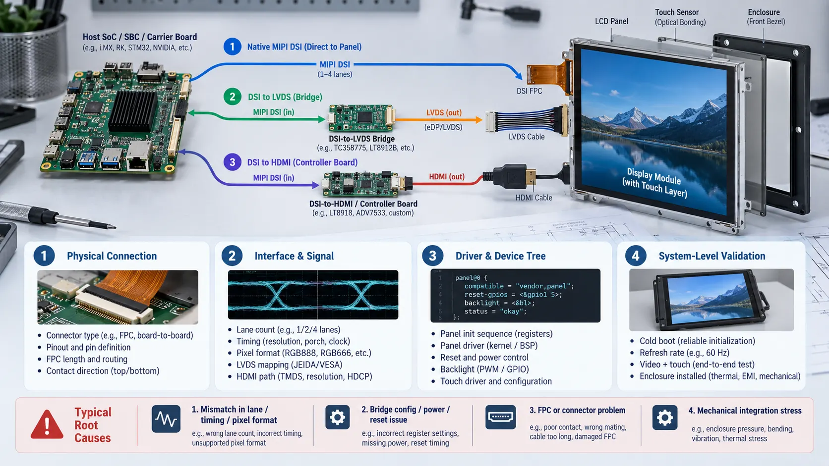
Native MIPI DSI, DSI-to-LVDS bridges, and DSI-to-HDMI architectures each serve different engineering requirements. Native MIPI DSI can simplify a compact design when the host processor and display panel are directly compatible. A DSI-to-LVDS bridge can connect a DSI-capable host to a suitable LVDS panel, while an HDMI-based architecture can simplify integration when a standardized video interface or existing HDMI controller board is preferred.
However, interface names alone do not guarantee compatibility. OEM engineering teams must evaluate the complete signal path, including the host processor, display panel, bridge circuitry, FPC, software drivers, touch controller, power sequence, and mechanical assembly.
In this guide, DINGTouch explains how to compare these three display architectures, identify common compatibility problems, select the appropriate corrective action, and prepare a production-ready display specification.
 Table of Contents
-
MIPI DSI vs. LVDS vs. HDMI Bridge: Quick Comparison
-
2.1 When to Choose Native MIPI DSI
-
2.2 When to Choose a DSI-to-LVDS Bridge
-
2.3 When to Choose a DSI-to-HDMI Architecture
-
-
Should You Change the Parameters, Display Module, FPC, PCBA, or Mechanical Design?
1. Recognizing Display Interface and Compatibility Problems
Display architecture problems often appear during the transition from an evaluation board to a customized product. A display may work under laboratory conditions but fail after the host board, cable, software, or enclosure changes.
Common symptoms include:
-
A native MIPI DSI display remains black when connected to a custom carrier board.
-
An HDMI monitor works correctly, but a bare MIPI DSI panel does not initialize.
-
An LVDS display has a functioning backlight but shows no image.
-
The display works at a lower refresh rate but becomes unstable at the target resolution or refresh rate.
-
Video output works normally, but the capacitive touch screen does not respond.
-
The image flickers or disappears after the display module is installed in the final enclosure.
-
The system starts inconsistently after a cold boot or power cycle.
These symptoms do not necessarily indicate a defective LCD panel or touch screen. The underlying problem may involve an interface mismatch, incorrect timing parameters, missing driver support, an incomplete bridge configuration, unstable power sequencing, FPC routing, or mechanical stress.
The first step is to identify which part of the display system is failing before replacing hardware.
2. MIPI DSI vs. LVDS vs. HDMI Bridge: Quick Comparison
The three architectures differ in how video data travels from the host processor to the display panel.
| Architecture | Best starting condition | Main engineering checks | Typical risk |
|---|---|---|---|
| Native MIPI DSI | The host provides a compatible DSI display output and the panel supports the required interface | Lane count, data rate, PHY, timing, initialization, driver and FPC | Interface and software incompatibility |
| DSI-to-LVDS bridge | The host provides MIPI DSI, but the selected panel uses LVDS | Bridge configuration, LVDS mapping, channel count, pixel clock, power and reset | Incorrect bridge or panel configuration |
| DSI-to-HDMI architecture | The product requires a standardized HDMI video connection or an existing HDMI controller board | Conversion direction, supported resolution, video configuration, power and touch connectivity | Confusing HDMI connectivity with direct bare-panel compatibility |
The most suitable architecture depends on the host platform, available display modules, development resources, system cost, mechanical constraints, and production requirements.
2.1 When to Choose Native MIPI DSI
Native MIPI DSI is often a practical choice for compact embedded products that require a direct connection between a compatible host processor and display panel.
It can reduce the need for additional conversion hardware and may simplify the physical design. This makes it worth evaluating for embedded Linux systems, single-board computers, industrial instruments, portable devices, and customized touch display assemblies.
Before selecting a native MIPI DSI panel, confirm the following:
-
The host has a MIPI DSI Display Host interface, not merely a MIPI CSI camera interface.
-
The required DSI lane count and lane data rate are supported.
-
The host and panel have compatible PHY requirements, resolution, refresh rate, and pixel format.
-
The panel's timing parameters and initialization sequence are available.
-
The operating system, kernel, board support package (BSP), and Device Tree support the selected panel.
-
The FPC connector, pin assignment, cable length, and installation route fit the mechanical design.
The main consideration is software and hardware bring-up. Two products can both use MIPI DSI while requiring different lane configurations, initialization commands, timing parameters, or driver implementations.
For OEM projects, native MIPI DSI should be selected only after the exact host and panel combination has been evaluated.
2.2 When to Choose a DSI-to-LVDS Bridge
A DSI-to-LVDS bridge can be useful when the host processor provides a MIPI DSI output but the preferred industrial LCD panel uses LVDS.
This architecture may be suitable when an OEM already has an established LVDS display design, needs to retain a particular panel, or wants to reuse an existing mechanical structure and panel supply chain.
The bridge converts the incoming DSI video stream into an LVDS output supported by the selected panel. However, the bridge must be compatible with both sides of the signal path.
Important verification points include:
-
DSI input lane count and supported data rate.
-
LVDS single-channel or dual-channel configuration.
-
VESA or JEIDA mapping requirements.
-
Pixel clock, resolution, refresh rate, and display timing.
-
Input and output pixel formats.
-
Bridge configuration method and initialization requirements.
-
Power rails, reset sequence, and backlight control.
-
Connector pinout, FPC routing, grounding, and electromagnetic compatibility.
An LVDS panel should not be assumed to work simply because a bridge is installed. The host, bridge, panel, and software configuration must operate as one coordinated system.
2.3 When to Choose a DSI-to-HDMI Architecture
A DSI-to-HDMI architecture may be appropriate when the system benefits from a standardized HDMI video connection or when an existing HDMI controller board simplifies product integration.
For example, an embedded Linux controller may provide MIPI DSI output, while the selected display assembly is designed to receive HDMI through a dedicated controller board.
In this case, the HDMI interface normally belongs to the controller-board level rather than directly to the bare TFT LCD panel.
Before selecting this architecture, confirm:
-
Whether the conversion path is DSI-to-HDMI or another direction.
-
Whether the host can supply the required DSI video stream.
-
Whether the bridge or controller board supports the target resolution and refresh rate.
-
Whether video configuration, EDID, or other display-identification mechanisms are required.
-
Whether the controller board needs additional power supplies or startup control.
-
How touch data returns to the host.
-
Whether the board, connectors, cables, and enclosure fit the final product.
HDMI carries video and, where supported, audio. Touch input typically requires a separate USB, I²C, or other supported communication path.
For products that prioritize convenient system integration over a minimal component count, an HDMI-based display assembly can be a practical option.
3. How to Diagnose a Display Architecture Problem
Before replacing the panel or redesigning the controller board, divide the fault into three areas: the host, the display signal path, and the touch/mechanical integration.
3.1 Check the Host Processor and Carrier Board
Start by confirming the exact host platform and its actual display output capability.
Ask the following questions:
-
Does the processor support a MIPI DSI Display Host?
-
Are the relevant interface pins routed to the carrier-board connector?
-
Are pin multiplexing, clock configuration, and lane settings correct?
-
Does the selected BSP support the display controller?
-
Is the required panel driver available for the operating system?
-
Does the development board use the same display interface as the production board?
A processor datasheet may identify a supported interface, but that does not automatically mean the interface is routed, enabled, or supported by the software on the production carrier board.
3.2 Check the Bridge, Display Panel, and Signal Path
If the host is correctly configured, inspect the entire display signal chain.
For native MIPI DSI, verify lane configuration, PHY requirements, timing, pixel format, and panel initialization.
For DSI-to-LVDS, also check the bridge configuration, LVDS channel selection, VESA or JEIDA mapping, and panel-side timing.
For DSI-to-HDMI, confirm the conversion direction, supported video modes, controller-board requirements, and any configuration or display-identification dependencies.
Also verify power rails, reset timing, and backlight enable signals. A working backlight does not prove that the video signal has been initialized correctly.
3.3 Check Touch, FPC, Connectors, and Mechanical Integration
Video and touch should be diagnosed as separate functional paths.
For the touch screen, check:
-
USB or I²C communication.
-
Touch-controller power and reset.
-
I²C address and bus configuration, where applicable.
-
Driver support and operating-system enumeration.
-
Touch FPC pinout and connector contact direction.
For the display interconnect, inspect the FPC length, connector pitch, locking mechanism, bend radius, grounding, and routing near other electrical components.
Finally, repeat the test after installing the display into the actual enclosure. Connector loading, cable bending, grounding changes, or cover-glass pressure can create problems that do not appear during an open-bench test.
4. Four Compatibility Layers to Verify Before Production
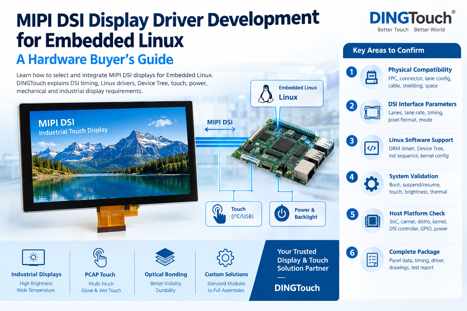
A production-ready display architecture requires more than a connector that physically fits. DINGTouch recommends verifying four compatibility layers in sequence.
4.1 Layer One: Physical Connection
Confirm that the host board, display module, bridge board, and FPC can be connected according to their respective specifications.
Document:
-
Connector manufacturer or series, pitch, and pin count.
-
Pin assignment and contact orientation.
-
FPC length, width, and bend requirements.
-
Power, ground, reset, and backlight pins.
-
Mounting positions and connector clearances.
Physical compatibility is the first checkpoint, not proof of complete electrical compatibility.
4.2 Layer Two: Interface and Signal Compatibility
Compare the electrical and video requirements of both sides of the interface.
For MIPI DSI, review lane count, data rate, PHY requirements, pixel format, timing, and initialization.
For LVDS, confirm channel count, mapping, pixel clock, signal levels, and connector pinout.
For HDMI, verify the controller or bridge input/output requirements, supported video modes, and configuration method.
Also confirm the panel's horizontal and vertical timing parameters, including sync widths and porch values, as applicable.
The host output and panel input must agree on the relevant parameters. A connector that fits correctly can still produce a black screen, corrupted image, or unstable refresh.
4.3 Layer Three: Driver, BSP, and Device Tree Compatibility
The software stack must correctly initialize the hardware.
Depending on the architecture and platform, review:
-
Display controller and bridge drivers.
-
Panel driver and initialization commands.
-
Device Tree nodes or overlays.
-
Lane configuration and display timing.
-
Reset GPIO and power sequencing.
-
Backlight control.
-
Touch-controller driver and communication interface.
For embedded Linux projects, confirm the actual kernel and BSP version rather than assuming that a driver available for one board will work unchanged on another.
A documented hardware interface and a reproducible initialization sequence can significantly reduce engineering time during integration.
4.4 Layer Four: Complete-System Validation
Once physical, electrical, and software compatibility have been established, validate the display in its intended operating environment.
Testing should include:
-
Cold boot and warm reboot.
-
Power cycling and recovery from shutdown.
-
Target resolution and refresh rate.
-
Video stability during continuous operation.
-
Touch response while video is active.
-
Final FPC routing and enclosure installation.
-
Operating-temperature requirements.
-
Relevant EMC and environmental tests.
The final approval should be based on the production-intent configuration, not solely on a development-board demonstration.
5. Common Causes of Display Initialization and Signal Failures
5.1 MIPI Lane, Timing, or Pixel-Format Mismatch
An incorrect lane count, data rate, or pixel format can prevent the panel from displaying an image correctly.
Timing mismatches may also cause instability at the target resolution or refresh rate. Problems can appear only under certain operating modes, making it important to test the complete timing configuration rather than relying on a single low-resolution test.
Recommended action: Compare the host configuration with the panel specification and verify the supported operating modes before changing hardware.
5.2 Bridge Configuration, Power, or Reset Failure
A DSI-to-LVDS or DSI-to-HDMI bridge may require a specific configuration sequence, power-up order, reset timing, or input/output setting.
If the bridge does not initialize correctly, the downstream panel may remain blank even when the host is producing a video stream.
Recommended action: Check the bridge documentation, configuration method, reset sequence, supply rails, and output status.
5.3 FPC, Connector, or Signal-Integrity Problems
An incorrect pinout, reversed contact direction, unsuitable cable length, damaged connector, or poorly controlled bend can interrupt signal transmission.
Signal integrity may also deteriorate when the cable route changes or the display is installed near sources of electromagnetic interference.
Recommended action: Inspect the interconnect against the approved drawing and validate the final cable route, grounding, and mechanical constraints.
5.4 Touch Works on the Bench but Fails After Installation
A capacitive touch panel may operate correctly on the bench but become unreliable after integration.
Possible causes include a disturbed I²C or USB connection, incorrect controller configuration, grounding changes, electrical noise, or mechanical pressure on the touch assembly.
Recommended action: Test the touch interface independently, then repeat the test with video active and the complete enclosure installed.
5.5 Mechanical Integration Changes Electrical Performance
Display architecture is also influenced by the physical design.
Mounting brackets, connector clearances, cover-glass pressure, cable routing, grounding, and housing materials can affect signal quality and touch behavior.
Recommended action: Include mechanical drawings and the intended FPC route during the early architecture review, rather than postponing mechanical validation until final assembly.
6. Should You Change the Parameters, Display Module, FPC, PCBA, or Mechanical Design?
The correct corrective action depends on the source of the mismatch. Replacing the entire display module is not always necessary.
6.1 Adjust Parameters When the Hardware Is Compatible
If the selected host, panel, and bridge support the same interface requirements, start by checking configuration errors.
Potential adjustments include:
-
DSI lane and data-rate settings.
-
Resolution and timing parameters.
-
Pixel format and supported refresh rate.
-
Panel initialization commands.
-
Bridge configuration.
-
Reset sequence and backlight control.
-
Device Tree and driver settings.
Parameter changes should follow the documented capabilities of the hardware. Software cannot resolve a fundamental electrical incompatibility.
6.2 Change the Display Module When the Interface Is Fundamentally Incompatible
A different panel or display module may be required when the selected module's interface, resolution, power requirements, or mechanical dimensions cannot be matched to the host.
For example, an OEM may need to select a different native MIPI DSI panel or use a suitable LVDS module with a validated conversion solution.
When evaluating an alternative, compare not only the interface but also brightness, viewing angle, operating temperature, touch requirements, availability, and lifecycle considerations.
6.3 Change the FPC When the Panel Is Suitable but the Interconnect Is Not
A revised FPC may solve problems involving:
-
Pin assignment.
-
Connector orientation.
-
Cable length.
-
Contact direction.
-
Bend radius and routing.
-
Mechanical interference.
-
Grounding and signal integrity.
The panel and host may remain unchanged if the electrical interface is correct and the interconnect is the actual source of failure.
6.4 Change the PCBA When Signal Conversion or Control Logic Is Required
A modified or custom PCBA may be appropriate when the product needs:
-
MIPI DSI-to-LVDS conversion.
-
MIPI DSI-to-HDMI conversion.
-
Dedicated display power management.
-
Bridge configuration and reset control.
-
Backlight control.
-
Touch-interface adaptation.
-
Additional system integration circuitry.
The additional board introduces component, layout, power, and validation requirements. Its benefits should be evaluated against the cost and complexity of a direct connection.
6.5 Change the Mechanical Structure When the Enclosure Causes the Failure
If the display works correctly before installation but fails after assembly, review the mechanical design.
Possible changes include adjusting mounting brackets, increasing connector clearance, revising the FPC route, reducing cable strain, improving grounding, or modifying the enclosure.
Mechanical changes should be verified through repeated assembly and system-level testing.
7. From a Standard Touch Display to a Customized HMI Solution
The appropriate solution level depends on how much of the display system is already defined.
7.1 Standard Display Module
A standard display module is a reasonable starting point when the host interface, resolution, mechanical envelope, and software support are already established.
It can reduce development effort, provided the selected module's specifications and integration requirements match the intended application.
7.2 Customized Touch Display Assembly
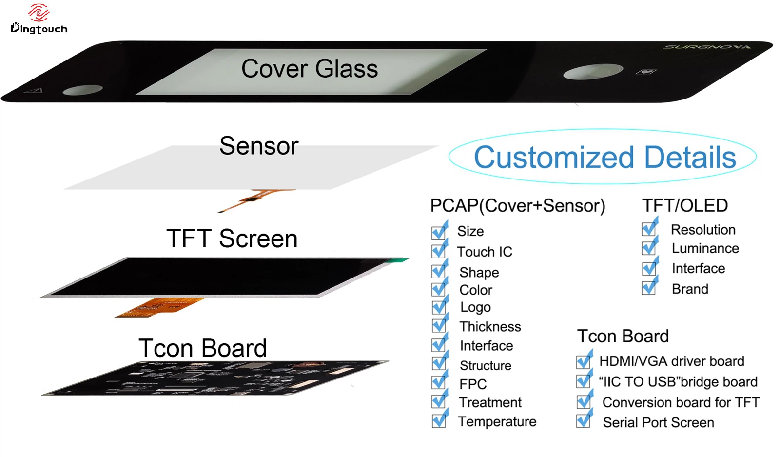
A customized display assembly may be more suitable when the project requires coordinated changes to:
-
LCD size, resolution, or brightness.
-
Projected capacitive touch technology.
-
Cover-glass dimensions and surface treatment.
-
Full optical bonding or other bonding methods.
-
FPC layout and connector position.
-
Touch-controller selection and tuning.
-
Display driver or controller PCBA.
-
Mechanical mounting and enclosure integration.
For industrial and medical equipment, the assembly may also need specific operating-temperature, durability, optical, and electromagnetic performance targets.
7.3 Integrated Display and HMI Solution
A more integrated HMI solution may be appropriate when the display, touch interface, controller electronics, cables, and mechanical components must be designed and validated together.
This approach is especially relevant to industrial control equipment, medical instruments, outdoor terminals, EV charging equipment, and embedded operator interfaces.
DINGTouch provides customized industrial capacitive touch screen and touch display solutions, including LCD and touch integration, cover-glass customization, optical bonding, FPC customization, and controller-board coordination.
The exact project scope should clearly distinguish display hardware, touch integration, host-side software development, certification, and final product validation.
8. OEM Display RFQ Checklist
A well-prepared request for quotation (RFQ) helps the display supplier evaluate feasibility, identify missing information, and recommend a suitable architecture.
Host and Software
-
Host SoC, SBC, or carrier-board model.
-
Operating system, kernel, and BSP version.
-
Available display outputs.
-
Current driver status and initialization documentation.
Display Requirements
-
Display size and resolution.
-
Required brightness and viewing angle.
-
Target refresh rate and pixel format.
-
Native MIPI DSI, LVDS, HDMI, or another interface.
-
Required operating and storage temperatures.
Electrical and Mechanical Details
-
DSI lane count and data rate, where applicable.
-
LVDS channel and mapping requirements, where applicable.
-
HDMI bridge or controller-board requirements.
-
Display timing and initialization sequence.
-
Power supply, reset, and backlight requirements.
-
FPC drawing, connector specification, and pinout.
-
Enclosure drawing, mounting points, and cable route.
Touch and Integration
-
Touch technology and controller requirements.
-
USB, I²C, or other touch interface.
-
Required touch-point count and glove or water operation.
-
Cover-glass dimensions and surface treatment.
-
Optical bonding requirements.
-
Touch tuning and grounding considerations.
Production and Validation
-
Application environment and operating conditions.
-
Target order quantity and expected production volume.
-
Prototype stage and development schedule.
-
Required EMC, environmental, or durability testing.
-
Failure photographs, boot logs, and test results for troubleshooting projects.
Providing these details early helps determine whether the project needs a standard module, a customized touch display assembly, a conversion PCBA, or a more integrated HMI solution.
9. Conclusion: Choose the Display Architecture That Fits the Complete System
Native MIPI DSI, DSI-to-LVDS, and DSI-to-HDMI architectures can all be effective choices for OEM display projects. The best option is the one that satisfies the host's capabilities, panel requirements, software support, mechanical constraints, and production targets.
Native MIPI DSI is worth considering when the host and panel are directly compatible. DSI-to-LVDS is useful when an LVDS panel is the practical choice, while an HDMI-based architecture can simplify integration when a standardized video connection or controller board is required.
Before releasing the design, verify physical connectivity, electrical signaling, software initialization, touch functionality, and final system operation.
DINGTouch supports customized Industrial touch screen and display projects from interface evaluation to display assembly integration. Share your host platform, display size, resolution, brightness, interface, touch requirements, operating conditions, and mechanical drawings to help evaluate a practical solution for your application.
Website: www.szdingtouch.com
Email: sales@szdingtouch.com
10. Frequently Asked Questions
10.1 Is a MIPI DSI Connector Enough to Guarantee Display Compatibility?
No. Compatibility also depends on lane count, data rate, PHY requirements, timing, pixel format, initialization commands, power sequencing, driver support, and the host's actual hardware implementation.
10.2 Does a DSI-to-HDMI Bridge Make Every HDMI Display Compatible?
No. The bridge must support the host's DSI output and the required HDMI video mode. The downstream display or controller board must also meet the resolution, refresh-rate, power, and configuration requirements. Touch input usually requires a separate communication path.
10.3 When Should an OEM Change the FPC Instead of the Display Module?
Change the FPC when the selected host and panel are electrically compatible but the cable pinout, length, connector orientation, contact direction, bend route, or mechanical installation is unsuitable.
10.4 When Is a DSI-to-LVDS Bridge Better Than a Native MIPI DSI Panel?
A DSI-to-LVDS bridge may be preferable when the required industrial LCD panel uses LVDS, an existing design is built around LVDS, or a suitable panel is more readily available in that interface. The complete bridge and panel configuration must still be validated.
10.5 What Information Should Be Included in a Custom Display RFQ?
Provide the host platform, operating system, display size, resolution, brightness, interface, timing information, touch specifications, FPC and connector details, mechanical drawings, operating conditions, production quantity, and validation requirements.
10.6 Can DINGTouch Customize a Display Module for an OEM Project?
Yes. Depending on project feasibility, DINGTouch can evaluate customized LCD and capacitive touch integration, cover glass, optical bonding, FPC, controller-board requirements, and mechanical integration. Final specifications and development scope should be confirmed against the project's technical requirements.
Ready to Build Your Outdoor Display Solution?
Get in touch with us at sales@szdingtouch.com. Our expert engineers will help you design a cost-effective, tailored solution to meet your project’s exact specifications.
DINGTouch :Committed to continuous innovation and improvement of product quality to meet customers' high requirements and expectations.
DINGTouch is a manufacturer that provides high quality touch screen panels. Focus on the design, manufacturing and sales of touch screen panels, and are committed to providing customized solutions that satisfy customers.
DINGTouch: In the process of customizing touch screen panels, we focus on close cooperation and communication with customers. Understanding customers' needs and providing customized solutions will meet customers' individual needs. The company's products are favored by customers for their high quality and reliability, and provide them with the best touchscreen panel solutions.
At DINGTOUCH, we are the world's leading touchscreen manufacturer, helping businesses around the world take advantage of this exciting technology. For more information, please visit the home page now.
DINGTouch is a company specializing in the R&D and production of touch screen technology, headquartered in Shenzhen, China. As a professional touch screen supplier, DINGTouch is committed to providing high-quality, stable and reliable touch screen products to meet the diverse needs of customers. We continue to carry out technological innovation and product optimization to ensure that its touch screen products have good sensitivity, accuracy and durability.
In addition to the products themselves, we also focus on cooperation and communication with customers, and are committed to providing customized solutions and excellent after-sales services. Through continuous efforts to improve product quality and customer satisfaction, we have established a good reputation in the touchscreen industry and won widespread market recognition.
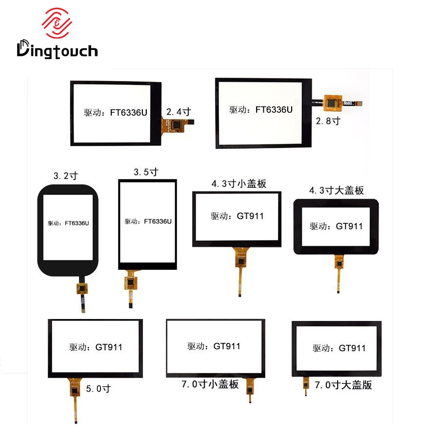
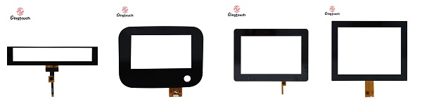
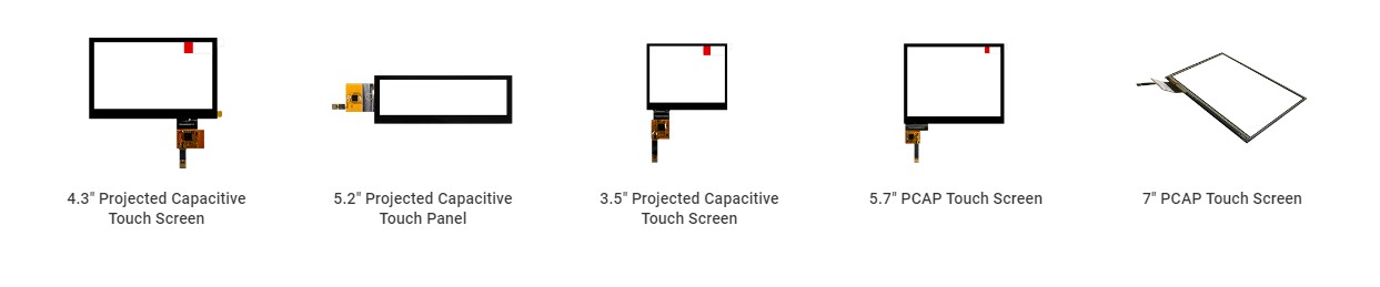
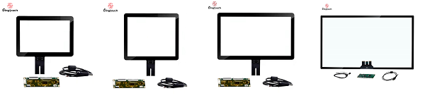
• PCAP maximum size 65”
• Multi-touch (Touch screen can be customized to your needs.)
• Optical bonding service/air bonding
• LCD interface: HDMI/RGB/MIPI/LVDS/EDP, etc.
• PCAP interface: IIC/USB interface
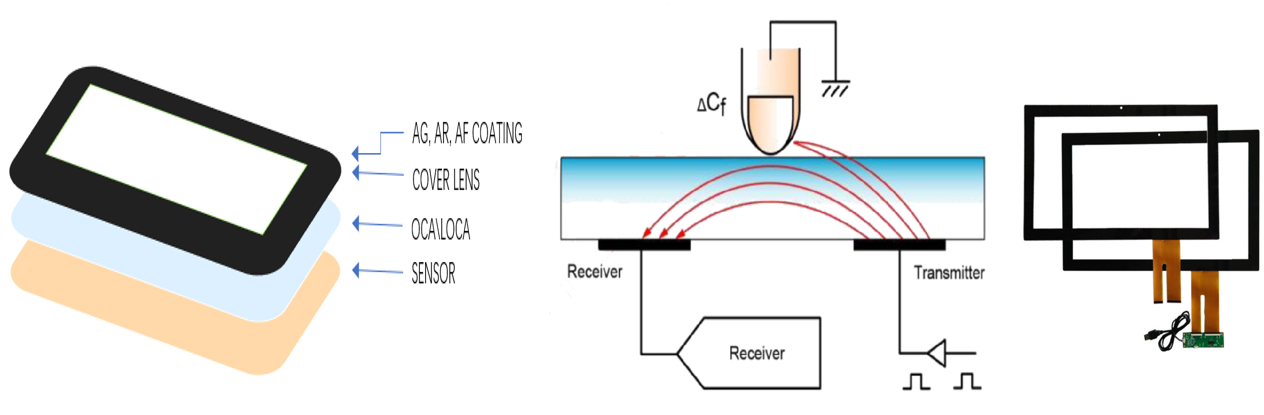
• CTP can customize the cover glass surface treatment process AG (anti-glare), AR (anti-reflection), AF (anti-fingerprint), waterproof, and glove touch
• Supports 0.55 mm-12 mm coverslip touch.
• Support operating temperature: -40℃-90℃.

Find the DINGTouch technical team to achieve the success of your company's new project.
What DINGTOUCH can do:

CATEGORIES
CONTACT US
Contact: Dingtouch
Phone: +8615815536116
Tel: +8615815536116
Email: sales@szdingtouch.com
Add: Building A, Bailu Plaza, No. 48, Gonghe Industrial Road, Gongle Community, Xixiang Street, Baoan District, Shenzhen,China. 518126
 Dingtouch