News
Optical Bonding Technology Explained: Display Structure, Materials, Manufacturing Process, and Common Defects

Optical Bonding for Touch Displays: Structure, Materials, Manufacturing Process, and Common Defects
A Practical Guide to OCA, LOCA, Full Lamination, and Display Bonding Quality
Optical bonding is an important manufacturing process used to improve the optical performance and mechanical integration of modern touch displays. By filling the air gap between the cover glass, touch panel, and LCD module with optical adhesive, optical bonding reduces internal reflections and helps improve display clarity, contrast, and touch interaction.
For industrial, medical, automotive, and outdoor display applications, optical bonding is not simply an additional assembly step. It is an engineering process that directly affects display readability, touch performance, structural reliability, and product quality.
At DINGTouch, optical bonding is part of our customized touch display manufacturing capabilities, integrating cover glass, capacitive touch panels, LCD modules, and bonding materials according to project requirements.
This article explains the fundamentals of optical bonding, including display structure, OCA and LOCA materials, manufacturing processes, equipment, common defects, and application considerations.
1. What Is Optical Bonding?
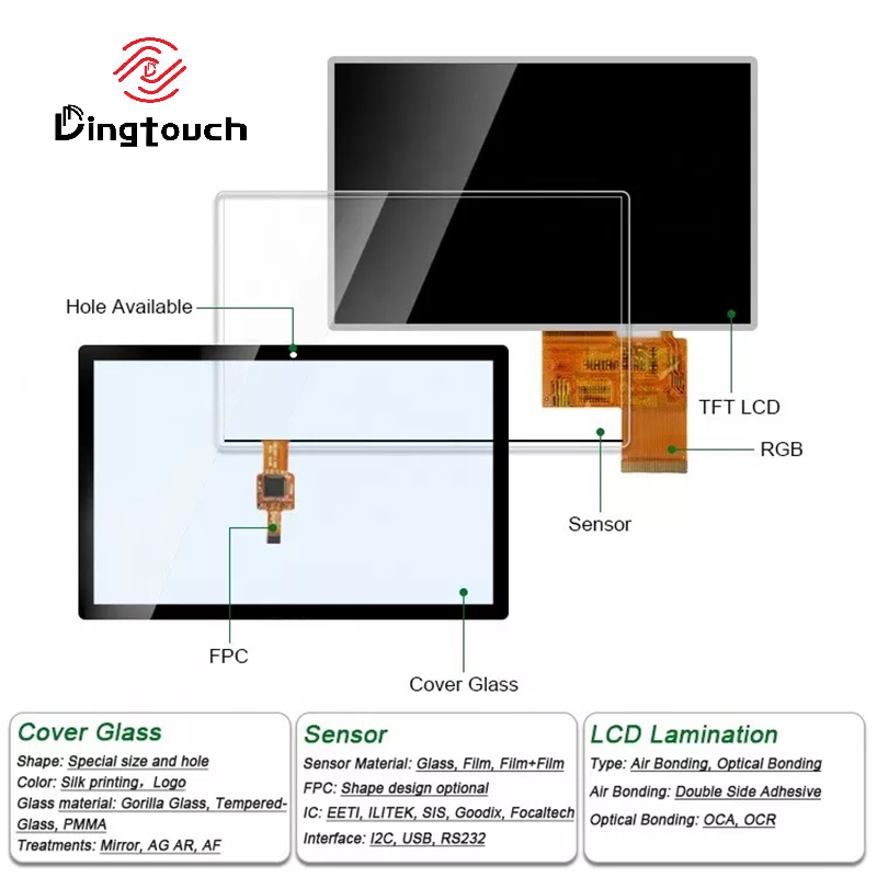
A typical touch display assembly consists of three main components:
-
Cover Glass (CG): Protects the display surface and provides mechanical strength, surface durability, and appearance.
-
Touch Panel (TP): Detects touch input and enables human-machine interaction.
-
Liquid Crystal Module (LCM): Generates the visual image.
Depending on the display design, the touch sensor may be integrated into the cover glass or incorporated into the display cell.
There are two common methods for assembling these components: frame bonding and optical bonding.
Frame Bonding
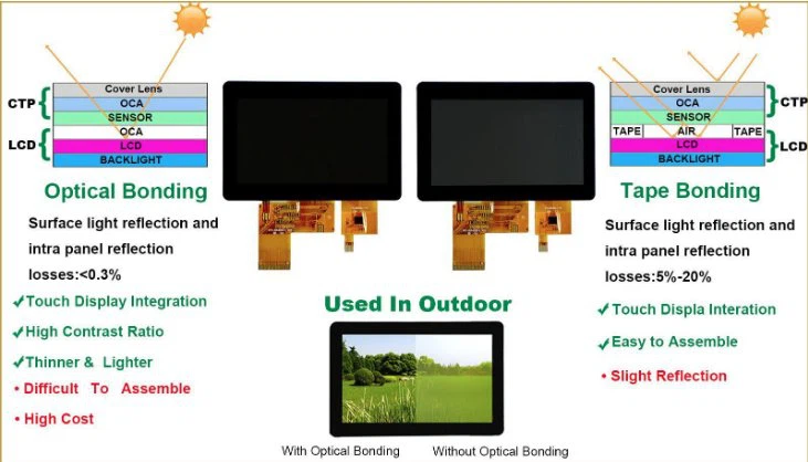
Frame bonding uses double-sided adhesive tape around the perimeter of the display assembly.
The adhesive fixes the touch panel or cover glass to the LCD module while leaving an air gap between the components.
This method offers a relatively simple manufacturing process, lower equipment investment, and easier component separation during repair.
However, the air gap creates additional optical interfaces. Reflections between the air and display materials may reduce perceived contrast and make the screen more difficult to read under strong ambient lighting.
Optical Bonding
Optical bonding uses transparent optical adhesive to bond the cover glass, touch panel, and display module across the intended bonding area.
A typical structure is:
Cover Glass (CG) → Optical Adhesive → Touch Panel (TP) → Optical Adhesive → LCD Module (LCM)
The actual structure depends on the touch technology and display design.
By eliminating the air gap, optical bonding can provide:
-
Improved display contrast.
-
Reduced internal reflections.
-
Better readability under ambient lighting.
-
Improved optical clarity.
-
More integrated mechanical construction.
-
Reduced risk of condensation within an exposed internal air cavity.
Optical bonding is particularly valuable for high-brightness industrial displays, medical equipment, automotive interfaces, and outdoor touchscreens.
However, it generally requires more specialized equipment, tighter process control, and greater attention to adhesive compatibility.
2. Optical Bonding Materials: OCA vs. LOCA
The optical adhesive is one of the most important factors affecting bonding quality.
The two common materials used in display optical bonding are OCA and LOCA.
OCA: Optically Clear Adhesive
OCA is a transparent pressure-sensitive adhesive supplied in film or sheet form.
It is widely used in display manufacturing because its thickness and material properties can be controlled during production.
Common OCA thicknesses include:
25 μm, 50 μm, 75 μm, 100 μm, and 125 μm.
The appropriate thickness depends on the bonding structure, surface geometry, adhesive properties, and required mechanical performance.
Advantages of OCA:
-
Consistent adhesive thickness.
-
Good optical transparency.
-
Convenient film-based lamination.
-
Suitable for automated bonding processes.
-
Repeatable manufacturing characteristics.
When selecting OCA, engineers should consider optical transmittance, haze, adhesion, elasticity, temperature resistance, UV resistance, and compatibility with the cover glass and touch sensor.
LOCA: Liquid Optically Clear Adhesive
LOCA is supplied in liquid form and applied directly to the bonding surface.
The adhesive spreads between the components before curing, allowing it to fill the intended bonding area.
A typical LOCA process includes:
Dispensing → Alignment → Lamination → Flow and Leveling → Inspection → UV Curing
Advantages of LOCA:
-
Flexible dispensing patterns.
-
Good conformity to selected surface geometries.
-
Potentially effective filling of surface steps.
-
Suitable for certain irregular or curved bonding structures.
However, LOCA requires precise control of dispensing volume, adhesive flow, component alignment, and curing conditions.
Excess adhesive may cause overflow, while insufficient adhesive may result in incomplete coverage or bubbles.
OCA vs. LOCA: Key Differences
| Feature | OCA | LOCA |
|---|---|---|
| Material form | Film or sheet | Liquid |
| Application | Film lamination | Adhesive dispensing |
| Thickness control | Defined by adhesive film | Depends on dispensing and bonding gap |
| Surface conformity | Depends on film properties | Can conform to selected geometries |
| Main process control | Alignment and lamination | Dispensing, flow, and curing |
| Equipment | Film lamination and bonding equipment | Dispensing, bonding, and curing equipment |
Neither OCA nor LOCA is universally better.
The correct material depends on the display structure, bonding area, cover glass geometry, optical requirements, production volume, and reliability targets.
3. Optical Bonding Manufacturing Process
Optical bonding requires careful control of component preparation, adhesive application, alignment, bonding, and inspection.
The process differs depending on whether OCA film or liquid LOCA is used.
3.1 OCA Film Bonding Process
OCA bonding typically follows these steps:
Step 1: Component Inspection
Inspect the cover glass, touch panel, and LCD module for scratches, contamination, dimensional defects, and electrical abnormalities.
Step 2: Surface Cleaning
Clean the bonding surfaces to remove dust, fingerprints, oil, and other contaminants.
Particles trapped between optical surfaces may create visible defects after bonding.
Step 3: OCA Lamination
Remove the appropriate release liner and laminate the OCA film onto the cover glass or touch panel.
The process requires controlled alignment and pressure.
Step 4: Component Alignment and Bonding
Remove the remaining release liner and align the LCD module with the touch assembly.
Bonding parameters should be adjusted according to the adhesive properties and product structure.
Step 5: Vacuum Bonding and Degassing
Depending on the material and assembly, vacuum bonding and subsequent degassing may be required to reduce trapped air.
Step 6: Inspection and Functional Testing
Inspect the bonded assembly for bubbles, dust, misalignment, adhesive overflow, and surface defects.
Electrical and touch functionality should also be verified.
3.2 LOCA Liquid Bonding Process
LOCA bonding requires additional control of adhesive dispensing and curing.
The typical process includes:
Step 1: Component Preparation
Inspect and clean the cover glass, touch panel, and LCD module.
Step 2: Adhesive Dispensing
Dispense the specified quantity of LOCA onto the bonding surface.
The dispensing pattern and volume depend on the bonding area, adhesive viscosity, and required bond-line thickness.
Step 3: Alignment and Lamination
Position the components and laminate them under controlled conditions.
The adhesive spreads between the bonding surfaces.
Step 4: Flow and Leveling
Allow the adhesive to fill the intended bonding area.
Inspect for trapped air, uneven distribution, and adhesive overflow.
Step 5: UV Curing
Cure the adhesive using the specified UV wavelength, intensity, and exposure time.
Curing parameters must be compatible with the adhesive formulation and optical structure.
Step 6: Final Inspection
Inspect the assembly for bubbles, contamination, bonding defects, and adhesive overflow.
Complete touch and display functionality testing before the assembly proceeds to the next manufacturing stage.
4. Optical Bonding Equipment and Process Control
Different bonding structures require different equipment configurations.
Semi-Automatic Bonding Equipment
Semi-automatic systems combine manual component handling with mechanical or vacuum-assisted bonding.
They are suitable for:
-
Engineering samples.
-
Low-volume production.
-
Customized display assemblies.
-
Selected repair operations.
Advantages include flexible operation and lower initial equipment investment.
However, manual handling may introduce variation in alignment, adhesive placement, and bonding consistency.
Fully Automatic Optical Bonding Equipment
Fully automatic systems may integrate component loading, vision alignment, adhesive handling, lamination, and bonding.
Their advantages include:
-
Higher production efficiency.
-
Improved alignment consistency.
-
Better process repeatability.
-
Reduced manual handling.
-
Greater suitability for production-scale manufacturing.
Equipment investment is generally higher, and process performance still depends on material quality, product design, and manufacturing control.
Vacuum Degassing Equipment
Vacuum degassing is used in selected bonding processes to reduce trapped air.
Depending on the adhesive and assembly structure, the process may involve vacuum, temperature, pressure, or a combination of these conditions.
The purpose is to improve adhesive contact and reduce visible bubbles.
The required process settings must be established through material evaluation and process qualification.
There is no single vacuum or pressure setting suitable for every OCA or LOCA application.
5. Common Optical Bonding Defects and Their Causes
Optical bonding defects may affect display appearance, touch performance, and long-term reliability.
Understanding their causes is essential for improving manufacturing yield.
5.1 Bubbles
Bubbles are among the most common optical bonding defects.
They may appear as isolated bubbles, edge bubbles, bubble lines, or bubbles around printed ink areas.
Possible causes include:
-
Dust or surface contamination.
-
Incorrect lamination pressure.
-
Insufficient adhesive coverage.
-
Improper adhesive placement.
-
Surface irregularities.
-
Inadequate degassing.
-
Incompatible adhesive properties.
Bubbles around the cover glass black border may be associated with the height difference created by printed ink.
Potential improvements include optimizing adhesive thickness, evaluating adhesive conformity, controlling ink-step geometry, improving cleaning, and adjusting bonding conditions.
5.2 Dust and Foreign Particles
Particles trapped between bonding surfaces may appear as dark spots, bright spots, or visible contamination.
Common causes include:
-
Inadequate cleaning.
-
Poor environmental control.
-
Contaminated materials.
-
Improper handling.
-
Particles generated during component preparation.
Prevention requires controlled cleaning procedures, material protection, and inspection before bonding.
5.3 Misalignment
Misalignment occurs when the cover glass, touch panel, or LCD module is positioned incorrectly.
It may cause uneven borders, incorrect viewing-area positioning, or touch sensor mismatch.
Possible causes include inaccurate alignment references, fixture variation, component dimensional errors, and movement during lamination.
Appropriate alignment fixtures and dimensional inspection help improve consistency.
5.4 Adhesive Overflow
Adhesive overflow occurs when adhesive extends beyond the intended bonding area.
Possible causes include excessive dispensing volume, incorrect adhesive thickness, excessive pressure, or improper alignment.
For LOCA processes, dispensing volume and flow control are particularly important.
5.5 Delamination
Delamination occurs when adhesive separates from one or more bonding surfaces.
It may appear as edge lifting, local separation, or progressive bonding failure.
Possible causes include:
-
Poor surface preparation.
-
Adhesive incompatibility.
-
Insufficient curing.
-
Moisture exposure.
-
Thermal stress.
-
Mechanical loading.
For industrial and automotive applications, adhesion stability should be evaluated under the intended environmental conditions.
5.6 Optical Non-Uniformity
Uneven adhesive thickness, mechanical stress, bonding pressure, or LCD module characteristics may contribute to visible optical non-uniformity.
However, not all display mura originates from optical bonding.
The LCD module should be evaluated before and after bonding to identify whether the defect is caused by the display panel, adhesive, or assembly process.
5.7 Touch or Display Functionality Issues
After bonding, the assembly should be tested for touch accuracy, response, display performance, and electrical functionality.
Potential issues may result from touch sensor damage, FPC stress, connector problems, incorrect controller configuration, or excessive assembly pressure.
Visual inspection alone is not sufficient to confirm a reliable touch display assembly.
6. Optical Bonding Quality Control and Reliability
Optical bonding quality should be evaluated through appearance inspection, optical measurement, electrical testing, and environmental validation.
Appearance Inspection
Typical inspection items include:
-
Bubbles.
-
Dust.
-
Scratches.
-
Adhesive overflow.
-
Misalignment.
-
Edge defects.
-
Visible delamination.
Inspection criteria should be defined according to the product's viewing conditions and customer requirements.
Optical Performance
Depending on the application, testing may include:
-
Display brightness.
-
Optical transmittance.
-
Haze.
-
Contrast.
-
Reflection.
-
Viewing angle.
-
Display uniformity.
The final optical performance depends on the complete assembly, including the cover glass, adhesive, touch sensor, LCD module, and surface treatments.
Touch Function Testing
Touch testing should be performed after bonding.
Typical items include:
-
Touch accuracy.
-
Response.
-
Multi-touch functionality.
-
Edge performance.
-
Glove operation.
-
Controller communication.
For customized industrial displays, testing should use the intended touch controller and host system whenever possible.
Environmental Reliability Testing
Depending on the application, reliability testing may include:
-
High-temperature storage.
-
Low-temperature storage.
-
Temperature cycling.
-
High-temperature and high-humidity exposure.
-
Vibration.
-
Mechanical shock.
-
UV exposure.
-
Cleaning chemical compatibility.
Test conditions should be defined according to the product specification and applicable industry requirements.
Optical bonding should be validated as part of the complete display assembly rather than evaluated only as an adhesive process.
7. Optical Bonding Applications
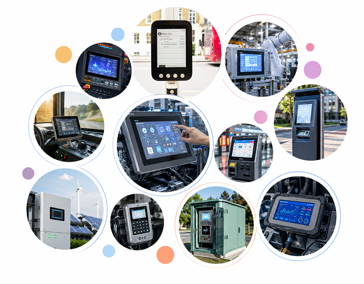
Optical bonding is widely used in applications where display readability, touch interaction, and mechanical integration are important.
Industrial Touch Displays
Industrial equipment may operate under bright lighting, vibration, dust, moisture, and temperature variation.
Optical bonding can improve readability and support a more integrated front-panel structure.
Applications include factory automation, CNC machine interfaces, industrial control panels, HMI terminals, and monitoring equipment.
The complete enclosure and sealing design must be validated separately to meet the required environmental protection level.
Medical Touch Displays
Medical equipment requires clear information presentation and reliable user interaction.
Applications include patient monitoring systems, diagnostic equipment, laboratory instruments, and medical device interfaces.
Optical bonding can reduce reflections and improve visual clarity.
Medical projects should also consider cleaning compatibility, glove operation, cover glass durability, touch performance, and applicable EMC requirements.
Automotive Displays
Automotive displays may experience vibration, temperature variation, and strong ambient lighting.
Optical bonding can improve visual integration and reduce internal reflections.
The bonding structure should be evaluated together with the cover glass, display module, mounting method, and mechanical design.
Outdoor and High-Brightness Displays
Outdoor displays may require high brightness, suitable surface treatments, and environmental protection.
Optical bonding helps reduce internal reflections, but outdoor readability also depends on brightness, anti-reflective treatment, viewing conditions, and display design.
The complete assembly should be evaluated for temperature, UV exposure, moisture, and mechanical reliability.
8. How to Select an Optical Bonding Solution
Selecting an optical bonding solution requires evaluating the complete display structure and application requirements.
Display Structure
Define:
-
Display size.
-
Cover glass thickness.
-
Touch sensor type.
-
LCD module structure.
-
Bonding area.
-
Printed ink border.
-
Surface coatings.
These factors determine the adhesive interface and bonding process.
Optical Requirements
Evaluate:
-
Brightness.
-
Ambient lighting.
-
Reflection.
-
Contrast.
-
Optical transmittance.
-
Surface treatment.
For high-brightness applications, optical bonding may be combined with anti-reflective or anti-glare treatments.
Environmental Requirements
Consider:
-
Operating temperature.
-
Storage temperature.
-
Humidity.
-
Vibration.
-
Shock.
-
UV exposure.
-
Water exposure.
-
Cleaning chemicals.
These requirements influence the selection of cover glass, adhesive, display module, and mechanical structure.
Manufacturing Feasibility
The bonding process should be compatible with the product dimensions, adhesive thickness, surface geometry, production volume, alignment requirements, and inspection methods.
For customized products, engineering samples should be used to verify the bonding structure before mass production.
9. DINGTouch Optical Bonding and Custom Touch Display Solutions
DINGTouch provides customized touch display solutions for industrial, medical, automotive, and commercial applications.
Our display integration capabilities include:
-
Capacitive touch panels.
-
TFT LCD modules.
-
Customized cover glass.
-
OCA optical bonding.
-
Full-lamination display assemblies.
-
Customized touch display structures.
-
High-brightness display configurations.
-
Industrial touch display solutions.
Depending on project requirements, the display assembly can be developed with customized cover glass dimensions, surface treatments, touch sensor configurations, display interfaces, and environmental specifications.
The engineering process begins with understanding the application and defining the display requirements.
Key project information includes display size, resolution, brightness, touch technology, cover glass thickness, bonding structure, operating temperature, interface, mechanical dimensions, and environmental conditions.
Based on these requirements, DINGTouch can evaluate the display structure, bonding materials, and manufacturing feasibility.
For customized optical bonding projects, engineering validation is important before production to ensure the assembly meets the required optical, electrical, mechanical, and environmental performance.
Conclusion
Optical bonding is an important technology for improving the optical performance and mechanical integration of modern touch displays.
By eliminating the air gap between the cover glass, touch panel, and display module, optical bonding can reduce internal reflections and improve display readability.
However, reliable optical bonding requires more than selecting OCA or LOCA.
The complete process involves display structure design, adhesive selection, surface preparation, precision alignment, lamination, degassing or curing, inspection, functional testing, and environmental validation.
For industrial, medical, automotive, and outdoor touch displays, these factors must be considered together.
The key to successful optical bonding is creating a stable, optically optimized, and application-specific display assembly.
DINGTouch supports customized touch display projects integrating cover glass, capacitive touch panels, LCD modules, and optical bonding.
Contact DINGTouch to discuss your display structure, bonding materials, and manufacturing requirements.
DINGTouch – Custom touchscreen and Display Solutions
CATEGORIES
CONTACT US
Contact: Dingtouch
Phone: +8615815536116
Tel: +8615815536116
Email: sales@szdingtouch.com
Add: Building A, Bailu Plaza, No. 48, Gonghe Industrial Road, Gongle Community, Xixiang Street, Baoan District, Shenzhen,China. 518126
 Dingtouch