News
10.1-Inch Industrial Touch Display Solutions: High Brightness, Wide Temperature & Custom Integration
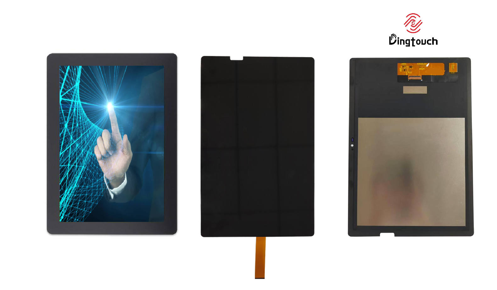 10.1-Inch Industrial Touch Display Solutions: High Brightness, Wide Temperature & Custom Integration
Industrial Display Design Goes Beyond Resolution
In industrial equipment development, selecting a display is not simply a matter of choosing the right screen size and resolution.
A display module must work reliably with the host processor, fit within the mechanical enclosure, provide sufficient brightness under different lighting conditions, and maintain stable touch performance across the intended operating temperature range.
For OEM manufacturers developing industrial control systems, medical equipment, outdoor terminals, and embedded human-machine interfaces (HMI), these requirements often lead to a need for customized display integration rather than a standard LCD module.
At DINGTouch, we focus on developing customized capacitive touchscreens, LCD display assemblies, cover glass, and optical bonding solutions for industrial and commercial applications.
Our engineering approach combines display selection, touch technology, interface integration, protective glass design, and mechanical evaluation to help customers develop display solutions that match their actual application requirements.
For projects requiring a 10.1-inch industrial display, DINGTouch can evaluate different resolution platforms, including 800 × 1280 and 1200 × 1920, according to the host interface, enclosure dimensions, display orientation, brightness requirements, and touch integration needs.
The objective is not simply to replace one display with another, but to identify a technically suitable display platform for the complete system.
1. Understanding the 10.1-Inch Industrial Display Requirements
A typical industrial display customization project involves several interconnected requirements.
The following specifications represent a reference configuration for engineering evaluation.
|
Parameter |
Reference Requirement |
|---|---|
|
Display size |
|
|
Resolution |
1280 × 800 |
|
Orientation |
Landscape |
|
Display technology |
IPS TFT LCD |
|
Interface |
4-Lane MIPI DSI |
|
FPC connector |
40-pin |
|
Connector reference |
HRS FH19-40S-0.5SH definition |
|
Brightness |
≥1000 cd/m², typical target |
|
Touch technology |
Capacitive touch |
|
Touch integration |
Optical bonding |
|
Alternative technology |
In-cell touch, subject to availability |
|
Cover glass |
AG + AF + UV protection |
|
Glass type |
Tempered / strengthened glass |
|
Operating temperature |
-30°C to +80°C |
|
Storage temperature |
-30°C to +80°C |
|
Reference LCM dimensions |
Approximately 229.5 × 149.1 × 4.7 mm |
These parameters should be evaluated as a complete system rather than as independent specifications.
For example, increasing cover glass thickness may improve mechanical protection, but it can also affect touch sensitivity, optical transmission, and the overall module thickness.
Similarly, increasing LCD brightness may improve visibility in bright environments, but it also introduces additional thermal and power considerations.
This is why DINGTouch recommends confirming the display, touch panel, cover glass, bonding structure, and mechanical dimensions together during the initial engineering evaluation.
2. Display Resolution and Orientation: Choosing the Right LCD Platform
Resolution is one of the first decisions in a customized industrial display project.
However, the correct resolution depends not only on the number of pixels, but also on the application interface, viewing orientation, enclosure design, and available display platforms.
For the reference project, the requested resolution is 1280 × 800 in landscape orientation.
This corresponds to a 16:10 aspect ratio.
DINGTouch can evaluate alternative display platforms based on the customer's application requirements.
2.1 800 × 1280: A Portrait-Native Display Platform
An 800 × 1280 display provides a portrait-native resolution.
Its advantages include:
-
Suitable for vertical interfaces and information-dense applications
-
Available as a potential platform for customized touch display development
-
Can be evaluated for landscape applications through display rotation
-
May provide an alternative when the original 1280 × 800 panel is unavailable
However, the resolution is not equivalent to 1280 × 800.
Although both contain 1,024,000 pixels, their pixel arrangements and aspect ratios differ.
For landscape applications, software rotation may be possible, but the effective display geometry, image scaling, interface timing, and mechanical fit must be evaluated.
Engineering consideration: A portrait-native panel should not be considered a direct replacement for a landscape-native panel without confirming the host system's display configuration.
2.2 1200 × 1920: A High-Resolution Display Platform
The 1200 × 1920 platform provides a higher pixel density and a different aspect ratio.
It may be suitable for applications requiring:
-
Detailed graphics and information presentation
-
High-resolution user interfaces
-
Portrait-oriented control systems
-
More detailed visual content
The total pixel count is 2,304,000, which is approximately 2.25 times that of the requested 1280 × 800 display.
This higher resolution may introduce additional requirements for:
-
MIPI DSI bandwidth
-
Host processor capability
-
Display timing configuration
-
Graphics rendering performance
-
Power consumption
-
Software adaptation
The display resolution alone does not determine whether the panel can operate with the customer's host board.
The MIPI lane configuration, supported pixel format, refresh rate, timing parameters, and driver compatibility must also be verified.
2.3 Why Resolution Compatibility Must Be Evaluated Early
For industrial display projects, resolution selection should consider three major factors:
Host compatibility
Can the processor and display controller support the required resolution, refresh rate, and interface timing?
Mechanical compatibility
Does the active display area and module outline fit the existing enclosure?
Application compatibility
Can the software support the display orientation, scaling, and user interface layout?
DINGTouch can evaluate these factors before finalizing the LCD platform, helping reduce unnecessary redesign during the prototype stage.
3. MIPI DSI Interface: 4-Lane Integration and 40-Pin FPC
The reference project specifies a 4-Lane MIPI DSI interface with a 40-pin FPC connector.
This interface configuration is important because the display must communicate directly with the customer's embedded processor or display controller.
The requested connector reference is HRS FH19-40S-0.5SH.
For customization, connector selection is only one part of the interface evaluation.
The complete FPC definition should include:
-
MIPI DSI data lanes
-
Clock lane
-
Power supply
-
Ground connections
-
Backlight power and control
-
Display enable and reset signals, where applicable
-
Touch interface signals
-
Touch interrupt and reset signals, if integrated
-
Connector pin assignment and electrical requirements
3.1 Connector Compatibility Is More Than Pin Count
A 40-pin connector does not automatically guarantee compatibility.
Even when two modules use the same connector series and pin count, their pin assignments may differ.
The following items should be confirmed before sample development:
|
Engineering Item |
Verification |
|---|---|
|
Connector |
HRS FH19-40S-0.5SH reference |
|
Pin assignment |
Confirm against host board definition |
|
MIPI lanes |
Verify 4-lane configuration |
|
Display timing |
Confirm supported resolution and refresh rate |
|
Voltage |
Verify LCD and interface power requirements |
|
Backlight |
Confirm power, enable, and dimming |
|
Touch interface |
Confirm USB, I²C, or other required connection |
|
FPC routing |
Confirm length, bending, and mechanical clearance |
For a customized display, DINGTouch recommends reviewing the host board's interface definition before selecting the final LCD module.
This is particularly important when considering a higher-resolution replacement.
A 1200 × 1920 panel may require a different MIPI DSI timing configuration and greater bandwidth than a 1280 × 800 display.
The final interface solution should therefore be confirmed through electrical documentation and prototype testing.
4. High-Brightness IPS Display: Designing for Better Visibility
The reference requirement specifies a typical brightness target of at least 1000 cd/m².
For industrial applications, brightness is an important factor in display readability.
However, the required brightness depends on the actual installation environment.
An indoor industrial control panel may operate under relatively controlled lighting conditions.
An outdoor terminal, vehicle-mounted display, or equipment exposed to strong ambient light may require a different brightness level.
4.1 Why IPS Technology Is Suitable for Industrial Applications
IPS TFT LCD technology is commonly used in industrial HMI applications where consistent image presentation and viewing-angle performance are important.
Its potential advantages include:
-
Wide viewing-angle performance
-
Stable image presentation
-
Suitable for landscape and portrait interfaces
-
Compatibility with industrial LCD module development
-
Flexible integration with capacitive touch panels
For applications where multiple operators view the screen from different positions, viewing-angle performance should be considered alongside brightness and contrast.
4.2 Brightness and Optical Bonding
The final brightness perceived by the user depends on the complete display structure.
A typical touch display may include:
-
Protective cover glass
-
Capacitive touch sensor
-
Optical adhesive
-
LCD module
When an air gap exists between layers, internal reflections may reduce optical clarity.
Optical bonding can reduce reflections at the interfaces and improve the perceived contrast of the display.
This is particularly useful when the display is installed in a bright environment.
However, optical bonding does not replace the need for adequate LCD brightness.
For a 1000 cd/m² target, the display brightness should be confirmed at the LCD module level, while the final bonded assembly should be evaluated for optical performance.
DINGTouch engineering recommendation: For high-brightness applications, evaluate LCD brightness, cover glass transmission, bonding materials, and surface treatments together rather than selecting the LCD based on its brightness specification alone.
5. Capacitive touchscreen Integration: G+G, Optical Bonding and In-Cell Options
Touch technology is another major part of the reference project.
The customer requires capacitive touch and optical full bonding, while also requesting an evaluation of an in-cell touch solution if available.
These technologies should be considered separately because they involve different integration structures.
5.1 External Capacitive Touch: G+G Structure
A conventional G+G capacitive touch panel consists of:
-
Cover glass
-
Capacitive touch sensor
-
Touch controller
-
FPC connection
The touch panel can be integrated with the LCD through optical bonding.
This structure provides flexibility for customized cover glass, surface treatments, touch controller selection, and mechanical design.
For industrial applications, it may be evaluated for:
-
Custom cover glass dimensions
-
Multi-point touch
-
Touch sensitivity adjustment
-
Glove operation
-
Water-related interference optimization
-
Customized FPC routing
The final performance depends on the touch controller, sensor design, cover glass thickness, grounding, and operating environment.
5.2 In-Cell Touch: A Different Integration Approach
In-cell touch integrates touch sensing into the LCD cell structure.
Compared with an external touch panel, it may reduce the number of separate layers and support a more integrated display design.
Potential advantages include:
-
Reduced external touch layer thickness
-
More integrated display structure
-
Potentially improved mechanical integration
-
Different optical and electrical characteristics
However, in-cell touch is not universally available for every display size, resolution, interface, or temperature requirement.
For this project, the feasibility of a 10.1-inch in-cell solution should be evaluated based on:
-
Available LCD platform
-
Native resolution
-
MIPI DSI interface
-
Touch controller and host communication
-
Cover glass compatibility
-
Operating temperature
-
Mechanical dimensions
-
Production availability
If a suitable in-cell platform cannot meet the complete specification, an external capacitive touch panel with optical bonding may provide a more practical customization route.
5.3 Optical Bonding: Improving the Complete Display Assembly
Optical bonding is particularly important when the display must operate in bright environments or when the front surface requires a protective glass structure.
DINGTouch can evaluate bonding structures using OCA or LOCA materials according to the panel design and manufacturing requirements.
The final bonding solution should consider:
-
Optical transmission
-
Reflection control
-
Adhesive compatibility
-
Bubble and contamination control
-
Temperature performance
-
Mechanical stress
-
Bonding thickness
-
Repair and manufacturing considerations
For a wide-temperature industrial display, the bonding material must be evaluated across the specified temperature range.
A bonding material suitable for room-temperature applications may not necessarily meet the requirements of a -30°C to +80°C industrial environment.
6. Protective Cover Glass: AG, AF, UV Protection and Strengthened Glass
The reference project requires a protective cover glass with:
-
AG treatment
-
AF treatment
-
UV protection
-
Tempered or strengthened glass
These treatments serve different purposes.
They should not be considered interchangeable.
6.1 AG: Anti-Glare Surface Treatment
Anti-glare treatment modifies the glass surface to reduce the appearance of reflected light.
It may help improve display readability under certain lighting conditions.
However, AG performance depends on the surface texture and treatment design.
The selection should consider:
-
Surface reflectance
-
Haze
-
Image sharpness
-
Brightness
-
Ambient lighting
-
Viewing distance
For industrial displays, excessive haze may reduce image clarity.
Therefore, AG treatment should be selected according to the actual display environment rather than simply choosing the highest haze value.
6.2 AF: Anti-Fingerprint Treatment
Anti-fingerprint treatment reduces the visibility and adhesion of fingerprints and oily contaminants.
It can improve the user experience for touch interfaces that are frequently operated.
Typical considerations include:
-
Surface cleanliness
-
Fingerprint visibility
-
Touch operation
-
Coating durability
-
Cleaning compatibility
-
Resistance to repeated handling
AF treatment is particularly relevant for industrial control panels, medical equipment interfaces, and public-facing terminals.
However, the coating performance should be verified against the customer's cleaning procedures and chemical exposure requirements.
6.3 UV Protection: Protecting the Display System
UV protection may be required when the display is exposed to sunlight or other ultraviolet sources.
The UV protection approach should be selected according to the application.
Possible considerations include:
-
UV transmission through the cover glass
-
Coating or material selection
-
Exposure duration
-
Optical transmission
-
LCD and touch component compatibility
-
Environmental aging
UV protection should be evaluated as part of the complete display system.
It is important to distinguish between UV protection for the cover glass and the overall resistance of the display assembly to long-term outdoor exposure.
6.4 Tempered and Chemically Strengthened Glass
Tempered glass and chemically strengthened glass use different strengthening processes.
Thermally tempered glass is strengthened through controlled heating and rapid cooling.
Chemically strengthened glass generally uses ion exchange to create a compressive stress layer near the surface.
The appropriate choice depends on the required:
-
Glass thickness
-
Mechanical impact resistance
-
Surface quality
-
Edge design
-
Optical performance
-
Application environment
For industrial touch displays, glass thickness should also be evaluated in relation to touch sensitivity and the mechanical structure.
A thicker cover glass may improve mechanical protection, but it can require touch controller adjustment and sensor optimization.
6.5 Cover Glass Thickness: Confirm Before Mechanical Design
The customer has not specified the exact cover glass thickness.
DINGTouch recommends determining it through mechanical and touch-performance evaluation.
The final thickness should be confirmed according to:
-
Enclosure design
-
Required mechanical protection
-
Touch sensitivity
-
Glass dimensions
-
Surface treatment
-
Bonding structure
-
Module thickness
The final drawing should clearly identify the cover glass thickness, total touch assembly thickness, and LCM thickness.
This is particularly important because the reference LCM thickness is approximately 4.7 mm, while the final bonded touch display may require a different overall thickness.
7. Wide-Temperature Design: -30°C to +80°C
Wide-temperature performance is one of the most important requirements for industrial display customization.
The reference project specifies:
-
Operating temperature: -30°C to +80°C
-
Storage temperature: -30°C to +80°C
These values should be evaluated separately.
Storage temperature indicates the environmental range the module can tolerate when not operating.
Operating temperature requires the display and touch system to function within the specified environmental conditions.
7.1 LCD Performance at Low Temperature
At low temperatures, LCD response characteristics may change.
Potential considerations include:
-
Slower response time
-
Changes in liquid crystal behavior
-
Backlight performance
-
Startup behavior
-
Touch response
-
Adhesive and bonding material characteristics
A display that meets the storage-temperature requirement does not automatically meet the operating-temperature requirement.
For industrial applications, the LCD, touch panel, FPC, controller, and bonding materials should all be evaluated.
7.2 High-Temperature Performance
At high temperatures, the display system may experience:
-
Backlight performance changes
-
Increased internal temperature
-
Optical variation
-
Adhesive aging
-
Touch controller temperature limitations
-
Mechanical expansion
High brightness can introduce additional thermal considerations.
For example, a display operating at 1000 cd/m² may generate more heat than a lower-brightness configuration, depending on the backlight design and operating conditions.
The final design should therefore consider brightness and temperature together.
7.3 Wide-Temperature touchscreen Engineering
The capacitive touch panel must also maintain reliable operation across the intended temperature range.
The evaluation may include:
-
Touch controller operating temperature
-
Sensor material characteristics
-
FPC and connector performance
-
Cover glass thickness
-
Touch sensitivity
-
Calibration
-
Noise immunity
-
Environmental testing
For applications involving gloves, moisture, or electrical interference, additional touch optimization may be required.
DINGTouch recommendation: A wide-temperature industrial touchscreen should be evaluated as a complete LCD + touch + bonding assembly, not simply by selecting an LCD with an extended-temperature specification.
8. Mechanical Integration: Matching the 229.5 × 149.1 × 4.7 mm Reference
The reference mechanical dimensions are approximately:
229.5 × 149.1 × 4.7 mm
These dimensions should be treated as the target LCM outline rather than an automatically confirmed final module size.
The mechanical evaluation should distinguish between:
-
LCD module dimensions
-
Active display area
-
Touch panel dimensions
-
Cover glass dimensions
-
FPC bending space
-
Connector position
-
Bonding thickness
-
Final assembly thickness
For a customized display, the cover glass may extend beyond the LCD module outline.
Therefore, the final touch display assembly can be larger than the LCM itself.
Mechanical Design Considerations
|
Item |
Engineering Consideration |
|---|---|
|
LCM outline |
Confirm actual panel dimensions |
|
Active area |
Confirm visible display area |
|
Cover glass |
Determine size and thickness |
|
Touch sensor |
Confirm sensor and bonding structure |
|
FPC |
Confirm connector, routing, and bending |
|
Mounting |
Confirm enclosure and fixing method |
|
Total thickness |
Evaluate LCD + touch + bonding |
|
Tolerance |
Confirm drawing and assembly requirements |
For projects requiring an existing enclosure, DINGTouch recommends confirming the mechanical drawing before finalizing the display platform.
This helps avoid unnecessary modifications to the customer's housing or host system.
9. DINGTouch Customization: From Display Selection to Engineering Validation
DINGTouch provides customized industrial touch display solutions for OEM and ODM projects.
Our engineering evaluation can cover the following areas.
Display Platform
-
LCD size and resolution
-
IPS display technology
-
Brightness selection
-
MIPI DSI interface
-
FPC and connector definition
-
Display orientation
-
Host compatibility
touchscreen Integration
-
Capacitive touch panel
-
G+G structure
-
In-cell feasibility evaluation
-
Touch controller selection
-
Touch sensitivity
-
Touch FPC
-
Optical bonding
Cover Glass Customization
-
Glass dimensions
-
Glass thickness
-
AG treatment
-
AF treatment
-
UV protection
-
Tempered or chemically strengthened glass
-
Customized appearance
Environmental Requirements
-
Operating temperature
-
Storage temperature
-
High-brightness operation
-
Touch stability
-
Bonding material compatibility
-
Environmental validation
Mechanical Integration
-
LCM outline
-
Touch panel outline
-
Cover glass dimensions
-
FPC routing
-
Connector position
-
Total thickness
-
Enclosure compatibility
Our goal is to help customers evaluate the most suitable display structure before moving into prototype development and production.
10. Engineering Recommendation for the Reference Project
Based on the customer's requirements, DINGTouch recommends evaluating the project in the following order.
-
Confirm the host interface
Review the 40-pin FPC definition, HRS FH19-40S-0.5SH reference, 4-Lane MIPI DSI configuration, and host board compatibility.
-
Select the LCD platform
Evaluate 800 × 1280 and 1200 × 1920 display options according to the required landscape orientation, enclosure dimensions, and host processor capabilities.
-
Confirm brightness and temperature
Verify whether the selected LCD platform can meet the ≥1000 cd/m² typical brightness target and -30°C to +80°C operating requirement.
-
Evaluate touch integration
Compare external capacitive touch with optical bonding against the feasibility of an in-cell touch solution.
-
Determine cover glass specifications
Confirm AG, AF, UV protection, strengthening process, glass thickness, and mechanical requirements.
-
Review mechanical drawings
Compare the selected display and touch assembly against the approximately 229.5 × 149.1 × 4.7 mm reference.
-
Validate the prototype
Evaluate display operation, touch response, interface compatibility, optical performance, and environmental requirements before production.
CATEGORIES
CONTACT US
Contact: Dingtouch
Phone: +8615815536116
Tel: +8615815536116
Email: sales@szdingtouch.com
Add: Building A, Bailu Plaza, No. 48, Gonghe Industrial Road, Gongle Community, Xixiang Street, Baoan District, Shenzhen,China. 518126
 Dingtouch